


SECTION 2
INSTALLATION
13
WARNING
DO NOT USE CONDUIT OR GAS LINE
FOR GROUND CONNECTION.
CAUTION
IT IS RECOMMENDED THAT THE OVEN
BE PLACED UNDER A VENTILATION
HOOD FOR ADEQUATE AIR SUPPLY
AND VENTILATION.
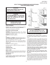
ELECTRIC SUPPLY TO BE
PROVIDED BY CUSTOMER
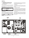
CIRCUIT BREAKER
Separate circuit breaker with lockout/tagout electrical
shutoff for each oven. Wire each oven separately.
15A Amp circuit breaker for 208-240V.
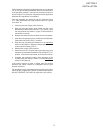
ELECTRICAL SPECIFICATIONS
DOMESTIC: 208V main blower motors, 1 Ph, 1.5 Amp
draw, 50/60 Hz, 208-240V control circuit, 2 pole, 3 wire
system per oven (2 hot, 1 grd).
Do NOT use conduit for ground.
or
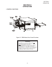
DOMESTIC or EXPORT: 240V main blower motors, 1
Ph, 1.5 Amp draw, 50/60 Hz, 208-240V control circuit, 2
pole, 3 wire system per oven (2 hot, 1 grd).
230V main blower motors, 1 Ph, 1.5 Amp draw, 50/60 Hz,
208-240V control circuit, 2 pole, 3 wire system per oven
(2 hot, 1 grd).
Do NOT use conduit for ground.
A 6 foot cord with a NEMA L6-20 plug is supplied on
Domestic units.
POWER RATING
50,000 BTU/hr (14.7 kW/hr.)
SUPPLY WIRE
Supply wire size must be in accordance with the National
Electrical Code (current edition) and must be in compli-
ance with local codes.
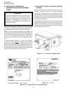
SUGGESTED
If space permits, service should be located near the
control console end of the oven(s) to allow convenient
access to safety switches.
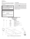
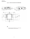
UTILITY ROUGH-IN DIMENSIONS AND POSITIONING
FOR PS528-SERIES OVENS
CAUTION
UNIT MUST HAVE AIR VENT PLATES
INSTALLED OR WARRANTY WILL BE VOID.
II. VENTILATION GUIDELINES
A mechanically driven ventilation system is required for
the PS528 Series Middleby Marshall conveyorized gas
ovens.
Local codes and conditions vary greatly from one area
to another and must be complied with. Following are
the suggested requirements for good ventilation. Please
remember these are recommendations or guidelines, you
may have a special condition or problem that will require
the services of a ventilation engineer or specialist. Proper
ventilation is the oven owner’s responsibility. Improper
ventilation can inhibit oven performance.
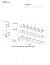
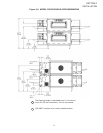
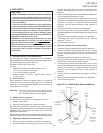
Please Note: There are now two “stand off” ‘C’ Chan-
nels and “Heat Guards” for “Double and Triple Ovens”
that must be installed in the eld.
Please Note: There is now one heat guard on dou-
ble units and two heat guards on triple units. See
Figure 2-7.
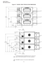
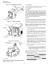
These ‘C’ Channel brackets are installed in the vertical
plane using existing screws (Item 6) to support these ‘C’
Channels using the upper and lower Key Hole openings
in the ‘C’ Channels. The ‘C’ Channels are identical and
once installed will allow ample amounts of air through
the cooling fan mounted on the rear side of the oven by
keeping the oven away from the rear wall.
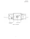
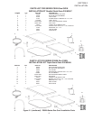
Figure 2-9. Typical PS528-Series Oven(s)
Installation