


11
CONVEYOR BELT REVERSAL
Conveyor belt reversal consists of four steps:
1. Physically reversing the conveyor belt.
2. Moving the lower thermocouple.
3. Resetting direction jumper on the conveyor control board.
4. Switching the photo detector.
REVERSING THE CONVEYOR BELT
Remove the conveyor from the oven and find the master link
location. Remove master links and remove the belt from the
conveyor frame. Reassemble the belt back onto the frame (in
the reverse direction) and reinstall the master links. Replace
the conveyor assembly in the oven.
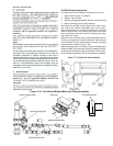
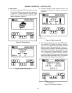
MOVING THE LOWER THERMOCOUPLE
The lower thermocouple needs to be moved from the lower
outer most hole to the opposite side lower outer most hole.
The thermocouple electrical connection needs to be moved
as well. Insert the thermocouple (TC2) into the thermocouple
hole left open by the removal of the coverplate. Secure the
thermocouple (TC2 and rename TC3) with the two (2) 6-32
screws that were removed previously. Secure the coverplate
with the two (2) 6-32 screws over the hole where the thermo-
couple (TC2) was removed.
RESETTING DIRECTION JUMPER
Locate Jumper P1 on the conveyor control board. Move jumper
from terminals 1 and 2, and replace onto terminals 2 and 3.
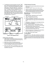
SWITCHING PHOTO DETECTOR
Remove both rear fan belt covers, then remove the motor cover
assembly from both sides of the oven. The photo eye is located
on the front side of the left motor bracket. Disconnect the three
connecting wires, noting which color wires assemble to the
associated wires on the photo-detector. Remove the entire
photo detector bracket. Replace the assembly to the right-
hand side of the unit, mirroring the way it was assembled on
the left. Reconnect the detector wiring in the same order it was
on the left.
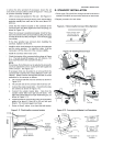
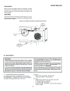
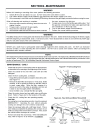
Incoming electrical power lines are fed through the strain-
relief fitting, shown in Figure 2-12. The electrical supply
connections are made inside the electrical junction box. The
power lines then connect to the oven circuits through safety
switches located inside the machinery compartment and
each blower motor compartment. These switches interrupt
electrical power to the oven when the Machinery Compart-
ment Access Panel is opened, OR when either of the blower
or rear shrouds is removed.
Mount the new reflector bracket to the provided holes on the
front right-hand side of the oven. The reflector should be
positioned just above the conveyor belt.
Using an assistant, hold both back cover switches in the
closed position. This will allow power to the photo-eye, and it
will provide a red beam for aiming. Loosen one of the screws
holding the photo detector gimbal tight, allowing it to be
reaimed at the reflector. The beam should hit exactly in the
center of the reflector, then tighten the screw back down.
Note: This is MUCH easier in reduced light.
Replace all covers.