


v
R evision R ecord........................................................................................................... i
L imited Warranty ......................................................................................................... iii
Forward........................................................................................................................ iv
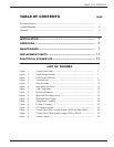
INSTALLATION ............................................................................ 1
OPERATION ................................................................................. 5
MAINTENANCE ........................................................................... 7
REPLACEMENT PARTS ............................................................... 13
ELECTRICAL SCHEMATICS ........................................................ 41
TAB LE OF C ONTE NT S
TABLE OF CONTENTS PAG E
LIST OF FIGURES
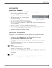
Figure 1 – Control Panel Detail ............................................................................... 5
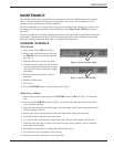
Figure 2 – Power Switch Position............................................................................ 7
Figure 3 – Drain Switch Position ............................................................................. 7
Figure 4 – Hood and Tank ........................................................................................ 14
Figure 5 – Door A ssembly ....................................................................................... 16
Figure 6 – Wash and Rinse Arms ............................................................................. 18
Figure 7 – Tank Components ................................................................................... 20
Figure 8 – R inse Aid Dispenser ............................................................................... 22
Figure 9 – Wash and Rinse Spray Arms .................................................................. 24
Figure 10 – Wash and R inse Piping ........................................................................... 26
Figure 11 – Pump/Motor Assembly ........................................................................... 28
Figure 12 – Booster Assembly .................................................................................. 30
Figure 13 – Fill Piping Assembly .............................................................................. 32
Figure 14 – Control Panel (Prior to Serial Number 54256 and After 54305)............ 34
Figure 15 – Control Panel (Serial Number R ange 54257 to 54304) ......................... 36
Figure 16 – Control Cabinet
......................................................................................
38