


LIST OF FIGURES (cont.)
Figure 9 – Drain Hose Connection............................................................................................. 13
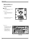
Figure 10 – Chemical Dispenser Signal Terminal Block ............................................................. 14
Figure 11 – Chemical Signal Connection Points ......................................................................... 14
Figure 12 – Detergent Probe Injection Points, 1/2" ..................................................................... 15
Figure 13 – Rinse Aid and Sanitizer Injection Points .................................................................. 15
Figure 14 – Fuses ......................................................................................................................... 28
Figure 15 – Motor Overload.........................................................................................................28
Figure 16 – Cycle Timer............................................................................................................... 29
Figure 17 – Cycle Timer Chart..................................................................................................... 29
Figure 18 – Fill Timer .................................................................................................................. 29
Figure 19 – Heater Element Wiring ............................................................................................. 30
Figure 20 – Pump Motor Wiring Diagrams ................................................................................. 31
Figure 21 – Pump Seal Replacement ........................................................................................... 32
Figure 22 – Doors and Panels ...................................................................................................... 34
Figure 23 – Door Guides, Stops and Lift Bracket........................................................................ 36
Figure 24 – Door Handle, Spring Assembly and Safety Switch .................................................. 38
Figure 25 – Track Assembly ........................................................................................................ 40
Figure 26 – Wash/Rinse Spray Piping..........................................................................................42
Figure 27 – Wash/Rinse Spray Arms ........................................................................................... 44
Figure 28 – Drain Assembly and Scrap Screens .......................................................................... 46
Figure 29 – Wash Tank Heat and Thermostats............................................................................. 48
Figure 30 – Electric Booster and Thermostats (MH-60 Only).....................................................50
Figure 31 – Lower Fill Piping Assembly (MH-60 Only) .............................................................52
Figure 32 – Upper Fill Piping Assembly (MH-60/6N Only) ....................................................... 54
Figure 33 – Lower Fill Piping Assembly (MH-6N/6L Only) ...................................................... 56
Figure 34 – Upper Fill Piping Assembly (MH-6L Only) ............................................................. 58
Figure 35 – Pump Assembly ........................................................................................................ 60
Figure 36 – Control Panel and Gauges.........................................................................................62
Figure 37 – Control Cabinet ......................................................................................................... 64
Figure 38 – Dishracks and PRV ................................................................................................... 66
Figure 39 – Three Phase Electrical Schematic .............................................................................69
Figure 40 – Single Phase Electrical Schematic ............................................................................ 70
CONTENTS
3