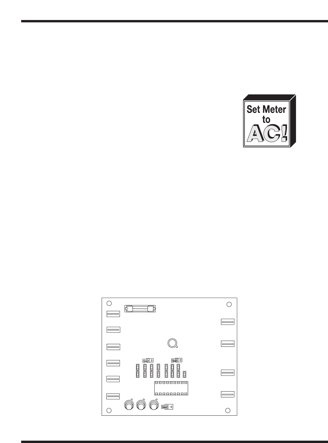
1.4 Testing Board Outputs
After you have verified that the circuit board is receiving power (as explained above), then test
the board outputs. There are 4 board outputs:
• Wash Cycle.
• Rinse Cycle.
• Heaters.
• In-Cycle Lamp.
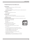
Perform the following steps to test a board output:
1. Set the voltmeter to measure AC volts.
2. Place the negative (black) test probe on the “neutral” terminal:
• T1, marked “N”.
3. Place the positive (red) test probe on the output terminal to be tested:
• T3, marked “WASH OUTPUT” (for the wash cycle) (doors must be closed before testing).
• T4, marked “RINSE OUTPUT” (for the rinse cycle) (doors must be closed before testing).
• T5, marked “HEATERS OUTPUT” (for the water heater).
• T6, marked “LAMP OUTPUT” (for the in-cycle lamp indicator).
4. Check the results on the voltmeter for the terminal you are testing:
• For T3 – the meter should read 120 VAC whenever the unit is in-cycle and the “WASH”
LED is illuminated on the circuit board.
• For T4 – the meter should read 120 VAC whenever the unit is in a fill or rinse mode and
the corresponding “FILL” or “RINSE” LED is illuminated on the circuit board.
• For T5 – the meter should read 120 VAC whenever the power switch is on and the wash
tank is full (i.e., the float switch is up).
• For T6 – the meter should read 120 VAC whenever the machine is in-cycle.
Figure 14
Solid State
Control Board
JB2
U1
L2
T10
T9
T8
T7
T1
T2
EXT. WASH
FLOAT SW.
FILL RINSE WASH
HEATERS
OUTPUT
LAMP
OUTPUT
T5
T6
T4
JB1
T3
WASH
OUTPUT
RINSE
OUTPUT
H
N
START SW.
DOOR SW.
F1
POWER
L1
L3 L4
JB3
BASIC SERVICE
26
BASIC SERVICE


