MQ-MIKASA MVH-702DRSC COMPACTOR — PARTS & OPERATION MANUAL — REV. #1 (12/17/03) — PAGE 19
MVH-702DRSC — REMOTE CONTROL COMPONENTS
TRANSMITTER
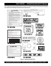
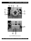
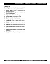
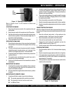
Figure 7 illustrates the location of the major components of the
transmitter. The function of each component is described below:
1. Joystick Lever – Controls the traveling speed and
direction of the machine.
2. Main Switch/ Emergency Stop – Immediately stops the
machine in an emergency.
3. Engine Switch –Starts and stops the engine.
4. Vibration Switch – Turns vibration on and off.
5. Signal Lamp – Infra-red monitoring lamp.
6. Battery Lamp - Lights to indicate that battery power is low.
7. Charge Lamp –Lights to indicate that the battery is
charging.
8. Cable Connection – Connector for remote control cable.
9.. Solar Cells - Used to charge unit by utilizing the sun’s solar
energy.
10. Signal Channel Control - Sets the operating channel of
the machine.
11. Battery Charging Connector - Connects battery charger
to transmitter.
12. Carrying Belt - Used by operator to carry remote control
transmitter.


