


µ
PD30500, 30500A, 30500B
2
Data Sheet U12031EJ3V0DS00
APPLICATIONS
• High-performance embedded systems
• Multimedia systems
• Entry-class computers
• Image processing systems
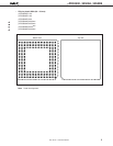
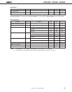
ORDERING INFORMATION
Part number Package Maximum operating frequency (MHz)
µ
PD30500RJ-150 223-pin ceramic PGA (48 × 48 mm) 150
µ
PD30500RJ-180 223-pin ceramic PGA (48 × 48 mm) 180
µ
PD30500RJ-200 223-pin ceramic PGA (48 × 48 mm) 200
µ
PD30500S2-150 272-pin plastic BGA (29 × 29 mm) 150
µ
PD30500S2-180 272-pin plastic BGA (29 × 29 mm) 180
µ
PD30500S2-200 272-pin plastic BGA (29 × 29 mm) 200
µ
PD30500AS2-200
Note
272-pin plastic BGA (29 × 29 mm) 200
µ
PD30500AS2-250
Note
272-pin plastic BGA (29 × 29 mm) 250
µ
PD30500BS2-250
Note
272-pin plastic BGA (29 × 29 mm) 250
µ
PD30500BS2-300
Note
272-pin plastic BGA (29 × 29 mm) 300
Note Under development
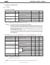
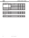
MAIN DIFFERENCES BETWEEN VR5000, VR5000A, AND VR5000B
Parameter VR5000 VR5000A
Note 1
VR5000B
Note 1
Maximum internal operating frequency
150/180/200 MHz 200/250 MHz 250/300 MHz
Internal multiplication ratio for clock 2, 3, 4, 5, 6, 7, 8 2, 2.5
Note 2
, 3, 4, 5, 6, 7, 8
interface input
Supply voltage 3.3 V ± 5% Core: 2.5 V ±5% Core: 1.8 V ±0.1 V
I/O : 3.3 V ±5% I/O : 3.3 V ±5%
Package • 223-pin ceramic PGA 272-pin plastic BGA
• 272-pin plastic BGA
Notes 1. Under development
2. Selectable only when SysClock = 100 MHz