


Owner’s Manual 14
Wiring Diagram and Pictorial
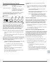
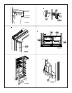
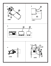
The parts of the ice maker wiring pictorial and diagram are (See
Art01500):
109 ..................................................... 120V AC Hot / smooth
110 ................................................. 120 VAC Neutral / ribbed
111 ................................................................... Ground screw
114 ................................................................... Thermal fuse
44 ......................................................... Solenoid water valve
115 ......................................................................... Ice maker
116 ...................................................................... Mold heater
96 ........................................................................ Thermostat
117 ................................................................. Shut off switch
118 ......................................................................... Fill switch
119 ...................................................................... Hold switch
120 ................................................................................ Motor
Ice Maker Wiring Pictorial and Diagram
(Optional)
Replacement Parts
You may purchase replacement parts through your local RV
dealer or authorized Norcold Service Center.
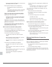
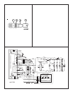
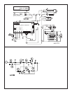
The parts of the wiring diagram are (See Art01769):
The parts of the wiring pictorial are (See Art01770):
A .................................................................... Temperature switch
B .................................................................................. AC heaters
C ..................................................................................Thermister
D ................................................................................ Interior light
E .............................................................................. Divider heater
F .............................................................................. Door contacts
G ............................................................................ Door switches
H ................................................................... Gas valve (optional)
I ............................................................................................. Fans
J ........................................Ice maker water line heater (optional)
K ...................................................... Water valve heater (optional)
L ...................................... Dispenser water line heater (optional)
M ................................... Dispenser water valve heater (optional)
N ......................................................... Dispenser valve (optional)
O ............................................................. Fan temperature switch
P ....................................................Temperature switch (optional)
Q ...................................................... Dispenser switch (optional)
R .......................................................... Dispenser light (optional)
S .......................................................................... Igniter (optional)
T .......................................................................... Chassis ground
U .......................................................... Movable door seal heater
V ............................................Movable door seal housing ground
1 ........................................................................ Switched 12 VDC
2 ......................................................... Fused continuous 12 VDC
3 ........................................................................ Communications
4 ............................................................................ Display ground
5 .......................................................................... Auxilliary ground
6 ...................................................................... Auxilliary +12 VDC
7 ......................................................................... Divider + 12 VDC
8 .................................................................... Gas valve + 12 VDC
F1 .......................................................................... 5 Amp DC fuse
F2 ........................................................................... 8 Amp AC fuse