


Installation and Owner’s Guide 10
Refrigeration Failure
If the refrigerator does not cool, it does not mean that the cooling
system is defective. Other items which effect the refrigerator
operation may be the cause of the problem.
If you notice a loss of cooling, do a check for a failure of either
the electric or propane gas controls as follows:
- Change the energy source of the refrigerator.
- If the refrigerator is operating on propane gas, change it
to electric operation.
- If the refrigerator is operating on electric, change it to
propane gas operation.
- Operate the refrigerator for several hours.
- Make sure the refrigerator is level within 3° side-to-side
and 6° front-to-back.
- Make sure the controls are in the correct position for the
energy source in use.
- Make sure the gas pressure is 11 inches Water Column
(10.5 in. W.C. min. - 11.5 in W.C. max.) and the voltage
is 120 volts AC (108 v. min. - 132 v. max.) (on model
323 only 12 volts DC, 11.5 volts min. - 15.4 volts max.)
- Make sure the air flow in the lower intake vent, through
the refrigerator cooling system, and out through the
upper exhaust vent is not blocked or decreased.
- If no cooling is occurs after about eight hours, contact your
dealer or a Norcold authorized service center.
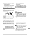
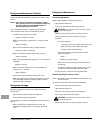
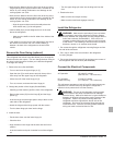
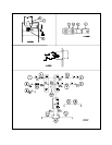
Wiring Pictorial
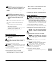
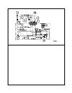
Wiring Diagram
Replacement Parts
You may purchase replacement parts through your local RV
dealer or Norcold authorized Service Center.
The parts of the wiring pictorial are (See Art00958):
1 ......................................................................... DC heater
2 ......................................................................... AC heater
3 ................................................................ Chassis ground
4 .................................................Thermocouple interrupter
5 ....................................................................... 3 Amp fuse
6 ..................................................................... 20 Amp fuse
7 .................................................................. Terminal block
8 ............................................................................. Jumper
9 ......................................................................... Thermstat
10 ............................................................................... witch
11.......................................................................... 120 VAC
12 .........................................................................12 VDC+
13 ....................................................................... Spark gap
The parts of the wiring diagram are (See Art00957):
1 ...........................................................................12 VDC+
2 ..................................................................... 20 Amp fuse
3 ......................................................................... DC heater
4 ..................................................................... 12 VDC com
5 ........................................................................... 120 VAC
6 ....................................................................... 3 Amp fuse
7 ......................................................................... AC heater
8 ..................................................................... 12 VDC com
9 ............................................................................. Ground
10 ..................................................................... Thermostat
11........................................................................ Spark gap
12 ................................................................... Piezo lighter
13 ....................................................................Safety valve
14 ................................................................ Thermocouple
15 ............................................... Thermocouple interrupter
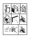
- Connect the DC wires from the refrigerator.
9. Connect the AC power cord to the receptacle.