


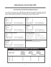

11
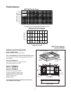
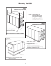
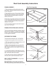
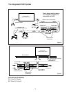
FRAME ASSEMBLY
1. Take one end piece (locking tabs) and one side
piece (slots). Stand both pieces vertically on the floor
or roof. See Figure 1.
2. Raise slightly the corner of the end piece (locking
tabs) and mate with side piece (slots), ensuring that
lower locking tab with leading edge is through slot
opening. See Figure 2.
3.Push down on top edge of end piece. Ensure that all
3 of the locking tabs are feeding into each correspond-
ing slot. Once both pieces are flush, the process is
complete. See Figure 3.
4. Drive one spike provided into wood nailer strips at
each corner. See Figure 3.
FRAME APPLICATION AND LOCATION
This roof mounting frame provides necessary support
when the unit is installed. The frame can be installed
directly on deck having adequate structural strength or
on roof supports under deck.
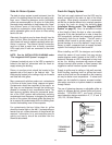
SECURING THE FRAME
To ensure proper mating with unit, it is critical that
mounting frame be squared to the roof, as follows:
1. With frame situated level in desired location on roof
trusses, tack weld one corner of frame.
2. Measure frame diagonally from one corner to the
opposite corner. Repeat with the remaining two cor-
ners. These dimensions must be equal for the frame
to be square.
3. It is extremely important to sight frame from all cor-
ners to ensure that the frame is not twisted across top
side. Shim frame under any low sides.
4. After frame has been squared, straightened and
shimmed, weld or attach frame securely to roof.
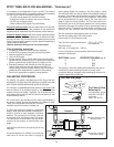
MAX. SLOPE TOLERANCE:
1/16" per linear
foot in any direction.
Note specification of duct location on bottom of
HRV when positioning cross members (duct cavity).
side piece
slot for tab
wood nailer strip
side piece
slot for tab
locking tab
spike
wood nailer strips
tabs through slots
end piece
wood nailer strip
end piece
locking tab
Roof Curb Assembly
Figure 1
Figure 2
Figure 3
Roof Curb Assembly Instructions