


12
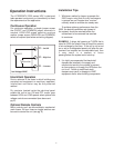
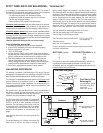
Drains
Connect the stainless steel drain pans in the bottom of
the HRV to a drain line fastened to the holes provided.
See pg.10 for location of the drain pans and the drain
connections. Create a "P" trap to prevent odours from
being drawn through. Make sure the drain line slopes
down to drain properly and if this is not possible a con-
densate pump will be required for removal of the water.
Note that stagnant water is a leading cause of indoor
air quality problems; confirm drainage after installation
by pouring water into trays. Drain line must be installed
where it will not freeze.
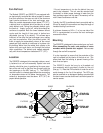
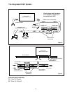
The Ductwork System
A well designed ducting system will allow the HRV to
operate at its maximum efficiency. Avoid the use of
undersized ducting and sharp radius bends and tees
which can significantly increase the system pressure
drop and reduce the air flows.
NOTE:
Fully insulated ducting with an integral vapour
barrier must be used on all runs passing
through unheated areas in order to avoid
condensation problems and energy losses
from the air streams.
* Consult local Codes
To minimize pressure drop and noise, galvanized metal
ducts sized for 1200 fpm (6.09 m/s). (maximum
velocity) are recommended. Keep ducting as short as
possible and use a minimum of elbows and tees.
Connecting sections and shorter runs may be flexible
ducting one size larger than the metal duct. Use
flexible duct connectors at the HRV to avoid noise
transmission.
All duct joints must be secured with screws, rivets or
duct sealant and sealed with aluminum duct tape to
prevent leakage.
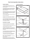
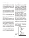
Outside Weatherhoods
The 2500EFD is shipped with 2 weatherhoods inside
the cabinet which attach to the outer ends of the cabi-
net using bolts provided. The 2500IFD requires hoods
to be built elsewhere and provided by the contractor.
The 2500EFD has built-in screens to prevent foreign
objects from entering into the ductwork through the out-
side hoods.
NOTE: It is extremely important to design and install
the fresh air intake in an area where the hoods will
gather the freshest air, free from restriction.
Recommended:
• no less than 10 ft. (3 m) apart from each other
• at least 18 in. (46 cm) above ground level
• away from sources of contaminants, such as
automobile exhaust fumes, gas meters,
garbage containers, cooling towers, etc.
• not exposed to prevailing winds, whenever
reasonably possible.
The outside perimeter of the weatherhood must be
caulked to prevent leakage into the building.
The design and size of the weatherhoods or louvers
chosen by the installer must allow for adequate free
area. Water and snow penetration of the system is min-
imized when the airflow does not exceed 750 FPM
(3.81m/s) free area velocity.
Ducting from the Weatherhoods
Galvanized sheet metal ducting with sufficient cross
section with an integral single piece vapour barrier
should be used to connect the HRV to the weather-
hoods.
All ducting must meet ULC Class 1 Fire Rating.
A minimum R value of insulation should be equal to 4
(RSI 0.75), or as stated in local codes.
A good bead of high quality caulking (preferably
acoustical sealant) and taping with a high quality alu-
minum foil tape is recommended to seal the duct to
both the HRV and the weatherhood.
Warmside Ducting -
General
Ducting from the HRV to different areas within the
building should be galvanized metal whenever
possible.
To minimize airflow losses in the ductwork system, all
ducts should be as short as possible and with as few
bends or elbows as possible. 45˚ elbows are preferred
to 90˚ elbows, whenever possible. Use Y tees instead
of 90˚ tees whenever possible.
All duct joints must be fastened securely and wrapped
with a quality duct tape to prevent leakage. We recom-
mend aluminum foil tape.