


13
Stale Air Return System
The stale air return system is used to draw air from the
points in the building where the worst air quality prob-
lems occur. Balancing dampers and/or adjustable
grilles are recommended on all return air lines which
are used during installation to help balance the "draw"
from different areas of the building. Note that the
installation schematics show balancing dampers
and/or adjustable grilles on all return air lines coming
back to the unit.
Alternately, the stale air may be drawn directly from the
return air duct. When this system is used the air han-
dler's blower will need to operate constantly when ven-
tilation is required. The exhaust takeoff connection
must be at least a meter from a directly connected
HRV supply duct if both are connected to the same
duct run.
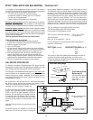
NOTE: See the INSTALLATION WARNING under
"The Integrated HVAC System" on page 16
A damper located just prior to the HRV is required to
balance the stale air exhausted with the fresh air
supply entering the building.
Return air suction points should be located at the
opposite side of the room to the fresh air inlet. The
inlets may be located in the ceiling or high on the walls
and fitted with inlet grilles.
Many commercial activities produce air contaminants
in the form of dusts, fumes, mists, vapours and gases.
Contaminants should be controlled at the source so
that they are not dispersed through the building nor
allowed to increase to toxic concentration levels. The
heat recovery ventilator allows for economical opera-
tion of the HVAC system while effectively removing
contaminants from the space. In designing the exhaust
portion of the system the exhaust grilles are placed so
as to remove the contaminants while not allowing them
to enter the breathing zone of the occupants.
For contaminants that are lighter than air, grilles
should be located high on the wall. If contaminants are
heavier than air, a lower placement of the grilles will be
required. Information on a contaminants specific
gravity and toxicity should be available from the
chemical data sheets.
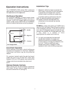
Fresh Air Supply System
The fresh air supply ductwork from the HRV may be
directly connected to the return air duct of the forced
air system. When directly connected it is recommend-
ed that the air handler blower be in constant operation
to move the fresh air about the building (see
Installation Warning under "The Integrated HVAC
System" on page 16). Also, it is advisable to include
a short length of fabric flex duct or other non-metallic
connector in this hard ducted line in order to keep the
HRV acoustically isolated and separately grounded
(electrically) from the air handler. This will avoid a
possible shock hazard to service people if a short to
ground develops in one of the devices. It may be nec-
essary to install a separate fresh air supply ductwork
system if the heating is other than forced air.
When installing an HRV, the designer and installer
should be aware of local codes that may require
smoke detectors and/or firestats in the HVAC or HRV
ductwork. Because an HRV is designed to bring fresh
air into the building, structures may require a supply
voltage interrupt when smoke or flame sensors are
triggered or central fire alarm system is activated.
Supply air grilles may be ceiling or high wall mounted.
Avoid locating incoming fresh air grilles that could
cause a direct draft on the occupants as the incoming
air may be below room temperature. A reheat duct
heater can be installed to improve occupant comfort.
Information on electric or hydronic heaters is available
through Nutech.
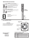
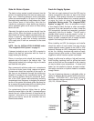
The use of balancing dampers or adjustable grilles as
supply air diffusers and air exhaust grilles are recom-
mended. TECHGRILLES™ are round, efficient,
sound absorbing devices available in 4", 5", 6" and 8"
(100, 125, 150 and 200mm).
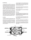
AIR FLOW
SUPPLY
AIR FLOW
EXHAUST
TECHGRILLE
(optional)
schematic