


2
QSC Audio Products, Inc.
QSControl.net™ Wall Control Plate Accessories
I. INTRODUCTION
The WCP-1 and WCP-2 are wall control plate accessories for QSControl.net
network audio system components, such as Basis, RAVE, and DSP
products. They allow an installer to create simple, non-computer user
interfaces for these products in sound systems. As a result, end users
don’t need to learn the QSControl.net software or anything technical about
the system to adjust volume, select audio sources, choose presets or
snapshots, or other control functions.
The WCP accessories connect to one or more of the unit’s OmniPort
inputs, which accept both analog control input via variable DC voltage or
variable resistance and digital control input via TTL-type logic.
The WCP accessories provide two ways to connect to the QSControl.net
unit: an RJ-45 jack, for use with Cat 5 or Cat 6 network cable, or a screw
terminal strip for use with individual wires.
Note: You must assign any
functions to their respective OmniPort inputs in the QSControl.net
VenueManager application.
Mounting
The WCP accessories mount in the type of plastic A/V wall box
commonly used in North America. They fit any Decora™-style trim plate.
The front panels have spaces for labeling functions, names, etc. Each
accessory comes with a sheet of labels printed with commonly used terms.
If you mount a WCP accessory in a metal electrical box, you may have
difficulty plugging a cable into the RJ-45 jack on the back of the
accessory.
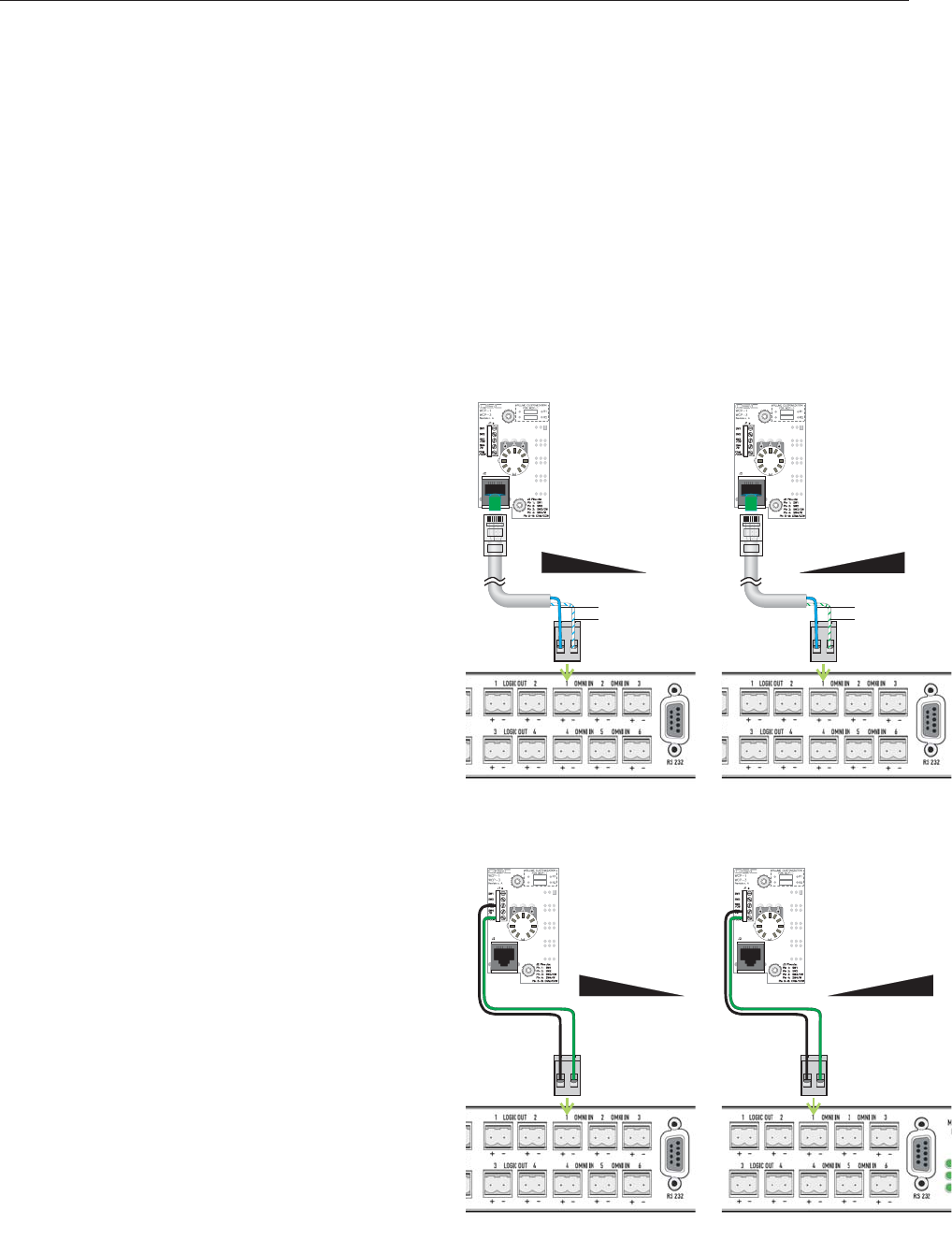
Resistance
min
max
CCW CW
Blue
White/blue
Resistance
min
max
CCW CW
Blue
White/green
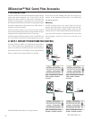
The control element of the WCP-1 is a 10 kΩ linear taper potentiometer
with 11 detents marked 0 (fully counterclockwise) to 10 (clockwise). It
connects to any OmniPort on the QSControl.net unit and can be wired so
that maximum resistance is at full clockwise
or
at full counterclockwise.
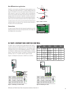
Figures 1–4 depict how to connect the WCP-1 to an OmniPort.
II. WCP-1 ROTARY POTENTIOMETER CONTROL
Resistance
min
max
CCW CW
Resistance
min
max
CCW CW
© 2005, 2007 QSC Audio Products, Inc. All rights reserved.
Figure 1. Connecting via network
cable; full CCW = maximum
resistance.
Figure 2. Connecting via network
cable; full CW = maximum
resistance.
Figure 3. Connecting via wires;
full CCW = maximum resistance.
Figure 4. Connecting via wires;
full CW = maximum resistance.