


3
QSControl.net™ Wall Control Plate Accessories Installation Guide Rev. B
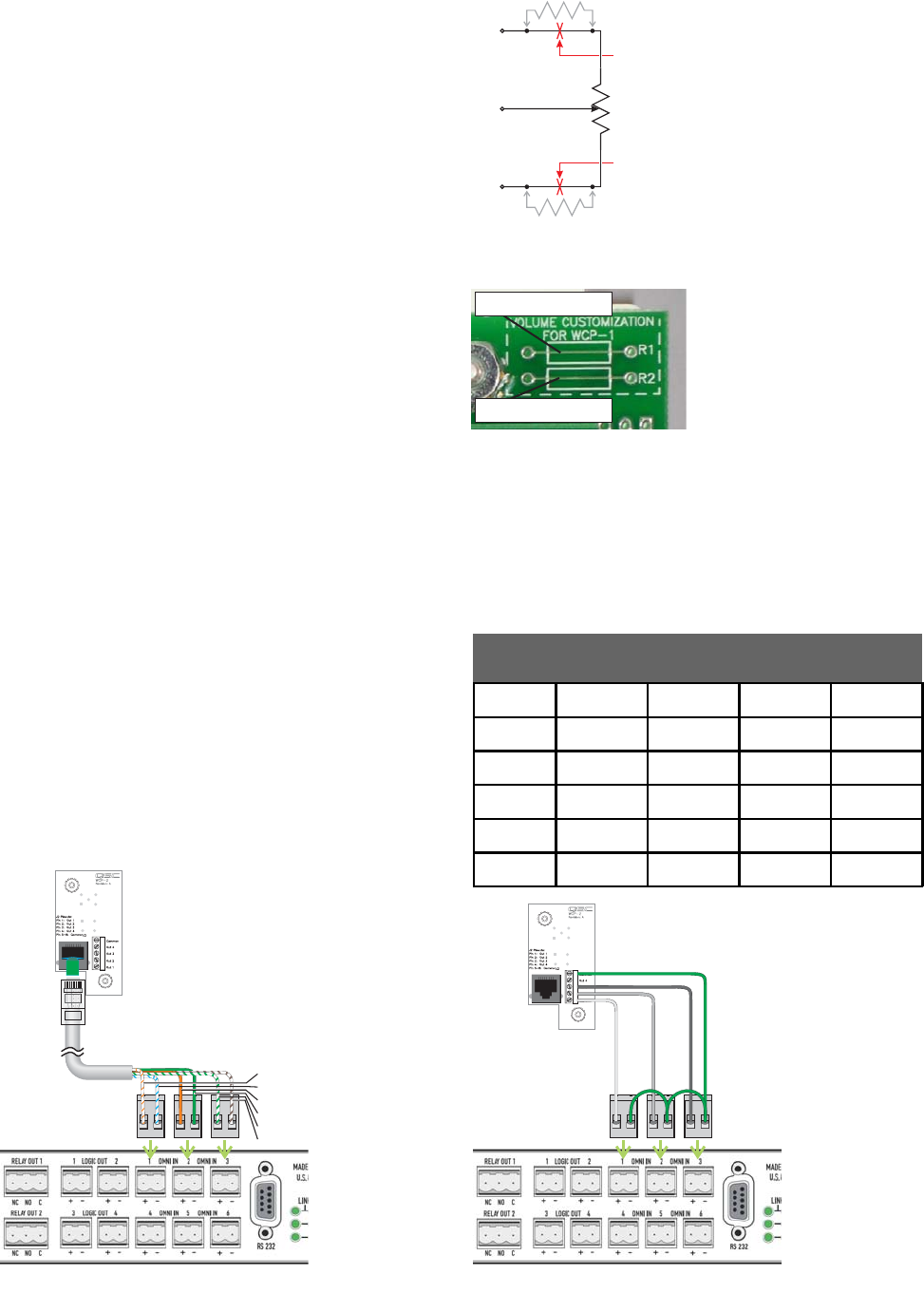
R2
R1
10K
CW
CCW
CW
CCW
Wiper
Cut here
to insert
resistor R2
Cut here
to insert
resistor R1
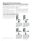
The WCP-2 uses a six-position binary-coded decimal rotary switch. It
connects to two (up to four usable positions) or three (up to six usable
positions) OmniPorts on the QSControl.net unit. The OmniPorts must be
configured for binary use in the VenueManager application. It is ideal for
such functions as selecting signal sources, selecting presets, and routing
signals. The truth table is at right. For reliability of interfacing with the
OmniPorts, there is no “0” position where all outputs are open.
Figures 7 and 8 depict the connection of a WCP-2 to an OmniPort.
III. WCP-2 ROTARY BCD SWITCH CONTROL
Position
▼
Out 1 Out 2 Out 3 Out 4
1Closed
Open Open Open
2 Open Closed Open Open
3ClosedClosed
Open Open
4
Open Open
Closed
Open
5Closed
Open
Closed
Open
6
Open
Closed Closed
Open
White/orange
White/blue
Orange
Green
White/green
White/brown
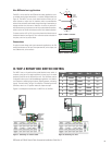
Non-QSControl.net applications
The WCP-1 can be used for non-QSControl.net analog applications, such
as variable passive signal attenuation or a variable voltage divider (see
Figure 5). The WCP-1 has two circuit board locations where you can
mount resistors to adjust the full clockwise and/or counterclockwise
values of the resistances and thereby change the range of attenuation or
voltage variation from minimum to maximum. A resistor in position R1
will add that amount of resistance to the fully counterclockwise position,
while a resistor at R2 will add resistance to the fully clockwise position.
To mount a resistor in R1 or R2, first cut the printed circuit board trace at
the desired location (see Figure 6). Then insert the resistor and solder it
into place, and trim any excess leads.
Connections
For typical control voltage and signal attenuation applications, the
CW
terminal would serve as the input; the
wiper
terminal, as the output; and
the
CCW
terminal, as the common.
Figure 5. WCP-1 schematic
Figure 6. Location of R1 and R2.
Cut this trace to add R2.
Cut this trace to add R1.
Figure 7. Connecting via network cable. Figure 8. Connecting via wires.