


- 13 -
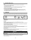
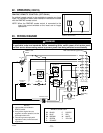
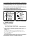
23. WIRING DIAGRAM
WARNING
Risk of electrical shock. Electrical wiring must be done by qualified personnel in accordance with
all applicable codes and standards. Before connecting wires, switch power off at service panel
and lock service disconnecting means to prevent power from being switched on accidentally.
!
120V, 60Hz
in
NOTES
1. Light socket not included in
RMIP33 model.
2. If any of the original wire, as
supplied, must be replaced, use the
same equivalent wire.
3. Field wiring must comply with
applicable codes, ordinances and
regulations.
LIGHT SOCKET LEFT
LIGHT SOCKET CENTER
LIGHTS
SWITCH
FAN SWITCH
SPEED CONTROL
TERMINAL BLOCK
FAN MOTOR
OUTLET
HS
THERMOSTAT
12
3
1
2
4
5
NEMA 5-15P
PLUG
Wall control remote by-pass Plug
LIGHT SOCKET RIGHT
NOTE 1
2
3
4
5
6
7
8
1
9
2
3
4
5
6
7
8
1
9
R
R
R
BL
BL
R
BK
BK
BK
BK
BK
W
W
W
W
W
W
W
W
W
G
BK
BN
BK
BK
nc
nc
O
BL
W
Y
W
O
O
W
BK
W
Grounding
plate
P
BN
P
Y
Y
WIRING COLOR CODE
BK BLACK
BN BROWN
BL BLUE
G GREEN
O ORANGE
P PURPLE
R RED
W WHITE
Y
YELLOW
BK
BK
BK
BK
BK
nc
HE0024A
Pin #9 is empty
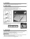
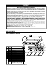
22. OPERATION (CONT’D)
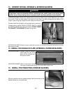
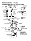
RMIPWC REMOTE CONTROL (OPTIONAL)
An optional remote control is also available to operate your hood
insert. For installation details, see installation instructions included
with the RMIPWC remote control.
NOTE: When the RMIPWC remote control is connected to the
insert, the control switches on the insert are no longer
operational.
HC0006
1
2
3
1) Light switch
2) Blower ON/OFF switch
3) Blower speed control