Tall chimneys may develop excessively high
updraughts which prevent the appliance operating
correctly.
It is recommended that a proprietary brand adjustable
flue draught stabiliser having an openable cross
sectional area of 126cm
2
be fitted above the flue pipe
connection, either in the brickwork or into a right angle
‘T’ fitting in the flue pipe position that will not
inconvenience appliance operation or maintenance.
Place the cooker in the intended position and lift out the
surface ground hotplate, checking that the joint between
the underside of the hob and the top of the cooker are
intact.
If the appliance is installed near combustible material
then as well as adhering to minimum clearances in Fig.
1 additional non-combustible insulation must be fitted to
the wall to protect the area around the flue and fluebox.
The insulation must reach a minimum distance of
150mm either side of the flue/flue box and follow the
line of the flue. The minimum specification for this
material is Superwool 607 LTI with a density of
320kg/m
3
, a thickness of 10mm and a self finish. There
must be a minimum 16mm air gap between the
insulation board and an adjacent combustible wall
surface. A higher specification material may be used
but the air gap must be maintained.
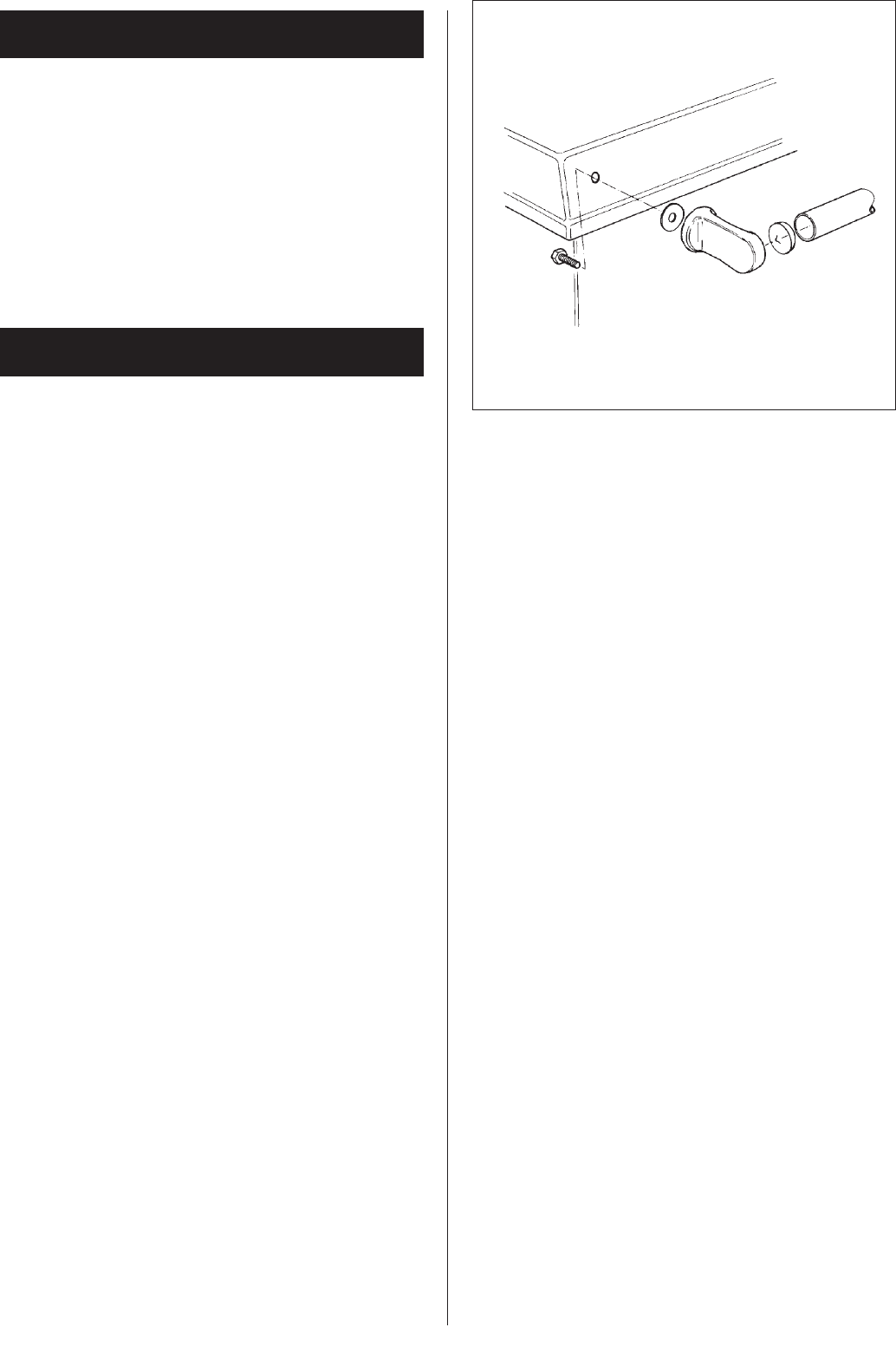
The handrail brackets are held on the front ends of the
cooker top-plate casting. Remove the travel nuts and
replace with the handrail brackets ensuring the fibre
protecting washers are in position. Insert the handrails
with fitted endcaps into the brackets, positioning them
correctly, and tighten the locating bolts (Fig. 8).
Any joints which have opened should be made good
with fire cement provided.
Replace the hotplate making sure that it is seating
evenly on the soft rope and that it is approximately
1.5mm proud of the enamelled top plate, with an equal
space all round.
Connect pipework to boiler flow and return tappings.
Fit the flue chamber which should be given a 1mm
smear of fire cement on the underside then screwed to
the cooker. Make sure there is a good seal between the
flue chamber and the cooker top (if there is an ingress
of air it can affect the flue draught and proper working of
the cooker). Before the fire cement hardens remove any
surplus with a damp cloth then polish with a dry cloth.
Open the firebox and ashpit doors and check that the
bottomgrate is in position. Operate the riddling lever to
ensure the bottomgrate operation.
Failure to do so can result in the enamel surface being
permanently marked.
The handrail brackets are held on the front end of the
cooker top-plate casting. Remove the travel nuts and
replace with the handrail brackets ensuring the fibre
protecting washers are in position. Insert the handrail
with fitted endcaps into the brackets, positioning them
correctly and tighten the locating bolts. (See Fig. 5).
INSTALLATION
6
Fig. 5 DESN 513152
HIGH UPDRAUGHTS


