3
What the installer will need
● A 13 Amp fused double pole isolating switch with a minimum contact gap of 3mm in each pole.
● Suitable length of 1.0mm
2
three core multi strand PVC insulated mains cable that complies
with BS6500.
● Suitable lengths of 15mm copper pipe.
Where to locate the SB
2
● We recommend that the unit is installed on a suitable wall, at shoulder height and over a
sink.
● Adjacent to the 13 Amp (240 V) double pole fused isolating switch.
● Available mains cold water supply and drainage facility.
● Do not install the SB
2
within reach of a person using a bath or shower.
● Do not obstruct the ventilation channel in the backplate.
Installing the water supply and steam vent pipes
The unit must be connected to cold, mains fed, drinking water only. Pressure range between 0.7
Bar/69kPa (10psi) and 10.0 Bar/940kPa (140psi).
Do not connect to a storage tank
● Isolate the water supply.
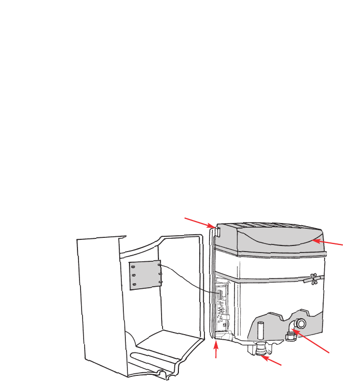
● Lay in 15mm water supply pipe to the location of the inlet connection (Fig. 1). (Check that
the water supply position gives enough space under the unit for it to be used properly).
Flush through the water supply before making the final connection, so that any debris is
removed.
Note: The inlet elbow contains a flow regulator. THIS MUST BE USED IN THE INSTALLATION.
● Lay in 15mm drainage pipe to the location of the steam vent connection (Fig. 1). (Connection is
made using the push fit adaptor provided).
● The steam vent connection must be taken directly to the sink below, if there is one, or via
a tundish to a suitable drain. Note: The steam vent outlet also acts as an overflow. (If a sink is
used it must be able to withstand boiling water and have an overfill outlet).
Fig. 1
Steam Vent
Ventilation Channel
Ventilation Channel
Inlet
Condenser


