


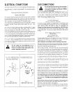

FIG.
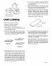
4
SHUT OFF VALVE HERE IF SHUT OFF VALVE HERE IF
REQUIRED BY LOCAL REGULATIONS
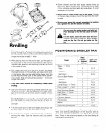
PRESSURE
REGULATOR
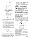
FIG. 5
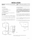
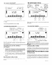
If
you are replacing an older unit that had a cutout height
of more than 38” (39” to 39-318” are normal, alternate
standards) follow steps below:
1.
Measure by how much your cutout height exceeds 38”.
2. Relocate and raise your gas inlet pipe if necessary. See
figure 4. The 2-112” dimension (shown in figure 4) need
only change if yourcu!out height is more than 38-l/2”. If
‘your cutout height is more than 38-l/2”, increase the 2-
1’2” dimension shown In figure 4 by amount measured
in step 1 I above.
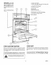
3. Remove the storage drawer (see Care and Cleaning
section of Use and Care Manual).
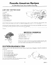
4. Extend the leg levelers (using a 3116” hex socket driver
or a flat bladed screw driver) by the amount measured in
step 1, above.
3.16 \
5. Insert the oven in the cutout and adjust leg levelers so
that oven racks are level (check with spirit level on oven
rack) and the top of the control panel overlaps the top of
the cutout.
6. Make electrical and gas connections and drive screws
through side trim as explained on previous page.
7.
TWO
lower trim pieces are provided. If you have extended
the leg levelers 34” or more, use the taller trim. Attach
to the unit with the 3 screws supplied and to the cabinet
below with the 2 wood screws supplied.
If leg levelers are extended less than 3/4”, use the
shorter trim. Attach to the unit with the 3 screws
supplied.
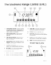
MAKING L.P. GAS ADJUSTMENTS
If you are using L.P. (bottled) gas all the
adjustments described below must be
made before you make any burner ad-
To adjust your oven for use with L.P. gas, follow the steps
below.
Step 1: Adjust Pressure Regulator
NOTE: The pressure regulator is set for natural gas. To
use L.P. gas, the regulator must be adjusted.
Locate the pressure regulator (see Fig. 5). Unscrew the cap
and remove the spring retainer, Fig. 6. Turn the retainer over
and put it back into the cap so L.P. is showing on the bottom
end of the retainer. Replace the cap.
Step 2: Adjust Burner Orifices
CAUTION:
The following adjustment must be made
before turning on the burners. Failure lo do so could
result in serious injury due to high flames and toxic
fumes.
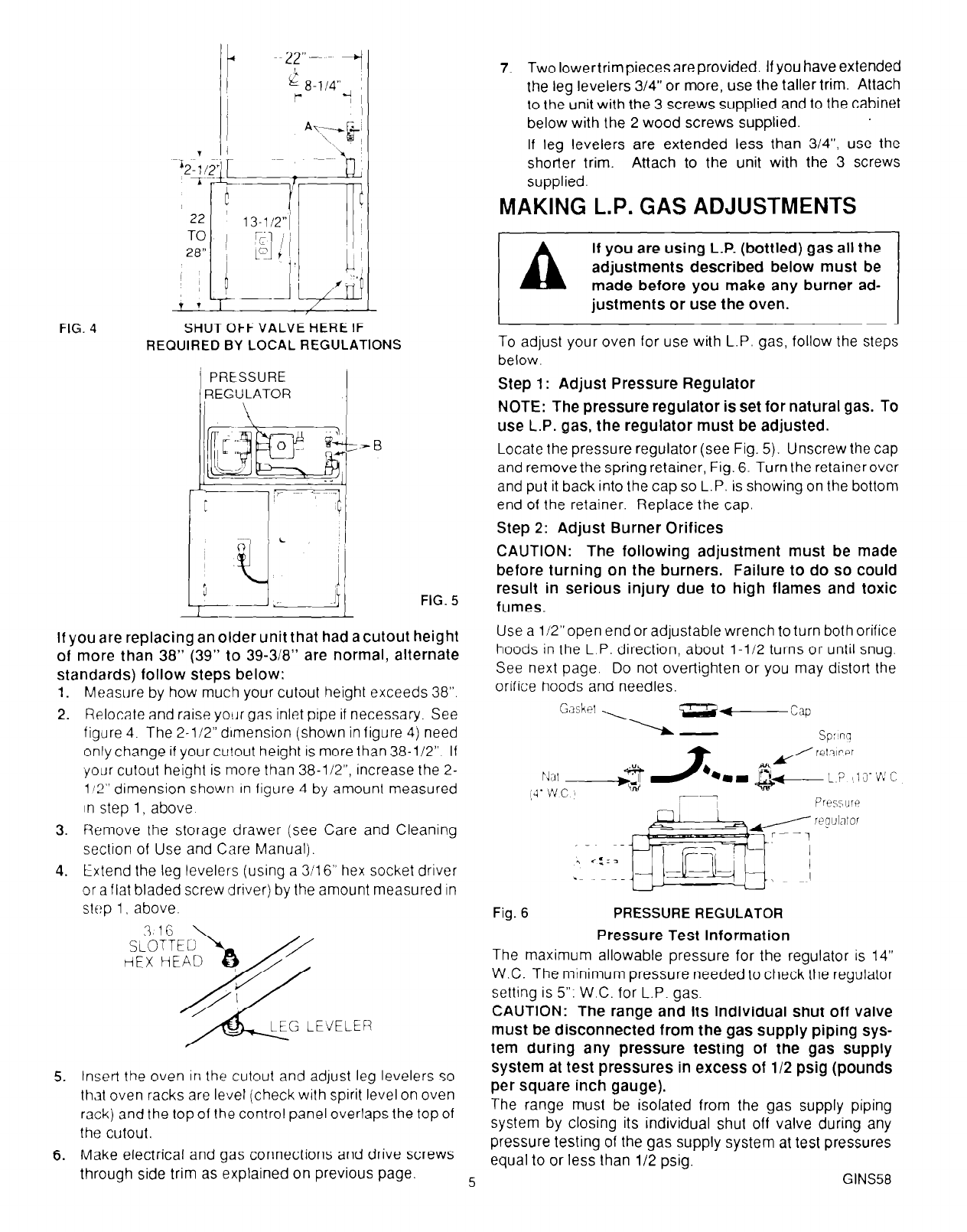
Use a li2”open end or adjustable wrench to turn both orifice
hoods in the L.P. direction, about l-l/2 turns or until snug.
See next page. Do not over-tighten or you may distort the
orifice hoods and needles.
Fig. 6
PRESSURE REGULATOR
Pressure Test Information
The maximum allowable pressure for the regulator is 14”
W.C. The minimum pressure needed to check the regulator
setting is 5”: W.C. for L.P. gas.
CAUTION:
The range and its individual shut off valve
must be disconnected from the gas supply piping sys-
tem during any pressure testing of the gas supply
system at test pressures in excess of 112 psig (pounds
per square inch gauge).
The range must be isolated from the gas supply piping
system by closing its individual shut off valve during any
pressure testing of the gas supply system at test pressures
equal to or less than l/2 psig.
5
GINS58