


),77,1*7+(9(17%2;
.
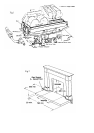
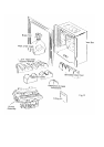
Position the box in the centre of the opening with a sufficient gap between the front flanges and the surround to
enable the tags on the rear of the brass trim to slide over. (Where a concealed gas supply is used feed the supply to
the position of the burner connection). The box is secured in place with the two 10x11/4 round headed screws and
plastic plugs supplied in the fitting kit using the two holes in the base of box. Replace the burner assembly in
position ensuring that the rear legs locate under the tags in the base plate and secure with the two screws provided.
Complete the gas connection to the burner as required and fit the brass trim by locating the tags in the cut outs in
the side flanges and sliding the trim down until the top tag locates over the top flange, remove the protective
plastic coating before lighting fire.
72&+(&.7+($33/,$1&(6(77,1*35(6685(/($.7(67
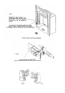
A Pressure Test Point at the inlet elbow enables verification of the inlet pressure of the appliance under operating
conditions and can also be used to check the gas soundness of the connections to the appliance gas control. To
check the joints of the burner assembly for gas soundness it will be necessary to carry out the examination prior to
installing into the case. If a manometer is used care must be taken to ensure that it is not disconnected with the gas
turned on and the fuel bed hot.
729(5,)<7+(,1/(735(6685(
The inlet pressure should be observed at 20mbar +/- 1mbar when the appliance is operating at its maximum rate.
Any significant reduction below an inlet pressure of 20mbar will indicate a restriction in the gas supply to the
appliance that should be identified and corrected. If there are any other appliances that are relatively high rated
(e.g. a central heating boiler) fed from the same gas supply branch, it is advisable to perform this observation with
both appliances in operation.
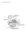
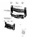
/2&$7,212)7+(),%5(%('
(See figure 13 for identification of components)
Position the two burner inserts between the front and rear ports of the burner, and place the simulated coal front in
position as shown in figure 7. The L&R Hand coal support shelves are positioned so that the rebated channel on
the under side locate over the rear flange of the fibre support channel. Two stops prevent the shelf closing the gap
between the back of the burner inserts and the front edge of the shelf; there should be a minimum gap of 6mm.
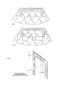
&2$//$<287
First Layer. Position 4 large coals with their rear edge on the burner inserts. Place 3 large coals at the rear of the
coal support shelf and lay 2 further at the sides of the shelf. These coals are placed on their edge. 3 more large
coals are placed on the coal support shelf to complete the first layer. See figure 8.
Second Layer. Two triangular coals are placed one either side ensuring that they rest against the side and
straddle the gap between the front and second row large coal. Position the remaining 5 medium coals in the
positions shown in figure 9.
To obtain the best visual appearance it may be necessary to make slight adjustments to the position of the coals.
NOTE: Additional coals must not be used. If any of the coals or the coal bed becomes damaged, lost or
broken, replacements must be obtained before the appliance is used
Page 6