


5
III. Hardware Description
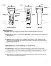
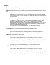
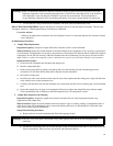
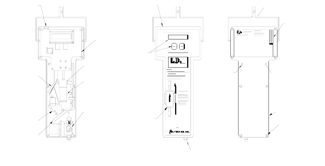
A. Instrument: The instrument houses the basic components required for operation of the ID900 as depicted above.
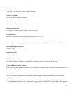
1. Case: an injection molded plastic housing that houses all internal components.
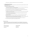
2. Hanger: connects into the side of the case and provides the user a means to hang the instrument above the working area for
hands free operation.
3. Sample Filter: will filter oil mists and particulate from the sample gas admitted into the instrument to provide trouble-free
function of the detection and sampling components.
4. Control Panel: consists of a 2-line, 16-character digital display and two pushbutton switches. The display will convey
analysis results and instructions to the user. The switches provide a means by which the user can communicate with the
instrument microprocessor during use.
5. Air Intake Port: will admit fresh air into the sampling system to permit calibration of the infrared and chemical fuel cell
detection devices.
6. Sample Exhaust Port: will emit sample gas that has been analyzed by the instrument.
7. Sample Inlet Port: permits the connection of either a R12 or R134a sample hose to the instrument.
8. Air Detection Sensor: a chemical fuel cell that will detect the amount of air contained within a refrigerant sample.
9. Control Circuit Board: directs all activities of the instrument through the embedded microprocessor. The infrared detection
device is also contained on this circuit board and will provide all detection of refrigerant components of the sample gas.
10. Purge Pump: will draw ambient air through the air intake port for the purpose of detection device calibration and
instrument sample system purging.
11. Power Connector: will accept the installation of either the standard vehicle battery adapter or the optional wall power
adapter to provide the instrument with operating power.
11. Power
Connector
11. Power
Connector
Sample filter exit
tube
10. Purge
Pump
Sample filter inle
t
valv
e
9.Control Circuit
Board
4. Control Pane
l
Sensor Housing
8.Air Detection
Sensor
InletPressure
Regulator
3. Sample filte
r
View with Cover Removed
Front View
Sample Inlet Port
A
ir Intake
Port
Hanger
Serial Number
Location
6. Sample exhaust
port
1. Case
Housing screws;
8 tota
l
Rear View