


22
OPERATION PRINCIPLES BY PARTS OF CIRCUIT
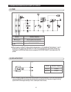
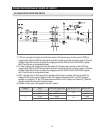
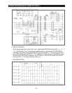
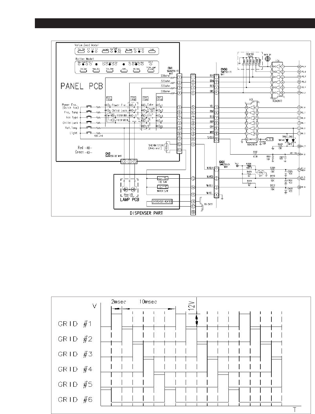
2) DISPLAY OPERATION
Like the signal diagram below, Micom sends “ high ” signal through MICOM 6 terminals of NO #1→ 2 → 3 → 4
→ 5 → 6 for 2ms every 12ms. This signal goes to output terminal via input terminal of IC5 (KID65783AP or
TD62783AP). Output wave always goes through LED input terminal with DC11~12V on every period. At this
time, if SINK signal comes out at IC4, DC11~ 12V is applied to LED input terminal and output terminal sinks to
OV which turn on LED for 2ms For example, to turn on "Power Fre." LED, IC4 #16 pin sinks to 0V when IC5
#16 becomes DC 11~12V making "Power Fre" LED turn on.
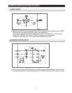
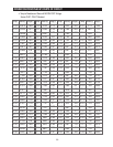
GRID WAVE PATTERN