


23
OPERATION PRINCIPLES BY PARTS OF CIRCUIT
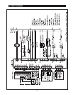
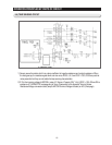
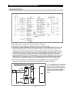
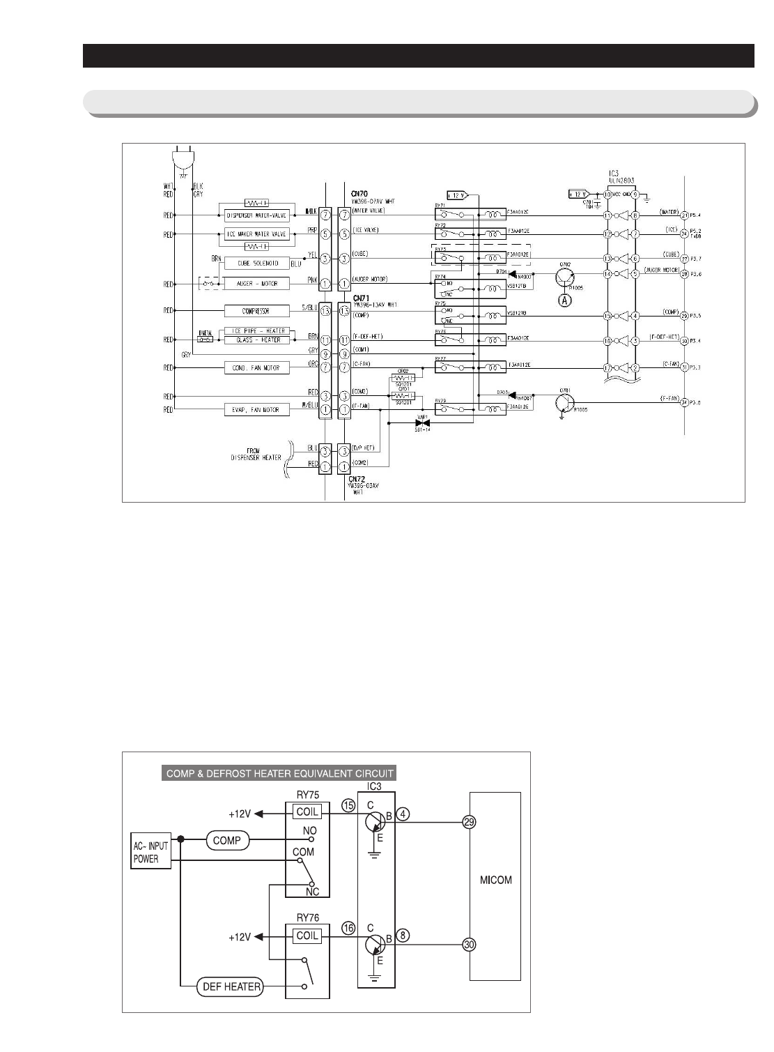
5-9) Load Control Circuit
1) Main PCB processes most of the load control for electronic refrigerators.
2) Compressor, F-Room, defrost heater, and other functions are controlled with relay.
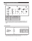
3) For example, to operate compressor, MICOM 29 pin outputs high (5V) signal which goes into IC3 Pin #4. The
IC3 pin NO 4 plays the same role as the base of NPN TR. The pin #14 works as collector of TR. So, if 5V is
supplied to pin #4 of IC3, the pin #15 turned on and connected to the ground. Then, the relay RY75 and coil
connected to the pin #15 of IC3 becomes low (OV) and +12V (opposite side of coil) flows to the pin #15 of IC3
via coil and goes into the ground. While current flows to the coil, the magnetic power arise, it turns on the
secondary contact point inside of RY75, and operates when the AC power is supplied to the both side of comp.
When MICOM #29 Pin becomes Low(0V), IC3 #4 Pin becomes Low which makes Power cut and current of
RY75 RELAY cut. So, secondary contact becomes off due to magnetic field cut, which makes Comp off.
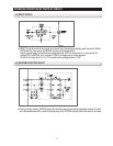
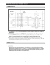
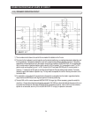
4) All other loads work basically on same principle, defrost heater operates only on the condition that the
compressor is turned off like the circuit above, and connected like the equivalent circuit below.
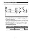
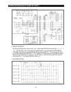
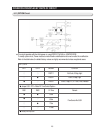
* Q710 is connected to the F door switch to
prevent PL accident due to continuous
operation of motor when the auger motor
control circuit is not working properly. It
must be turned off when the door is
opened.