


24
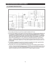
OPERATION PRINCIPLES BY PARTS OF CIRCUIT
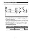
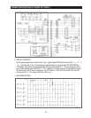
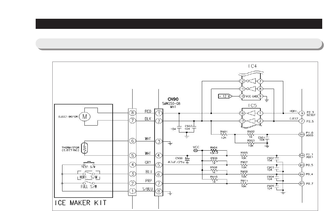
1) The ice maker circuit above is to control the ice maker kit installed on the F room.
2) This circuit is the hardware to control ejection and horizontal positioning, ice making temperature detection and
full icing detection. Temperature detection circuit is the same as temperature detection circuit on 4-6 and the
explanation will be skipped and only the ejection circuit will be explained. If MICOM PORT #7 is outputted with
High to rotate motor in ejection direction and the pin #2 of IC5 is inputted, 12V is outputted on pin #17 of IC5,
goes to motor and supplied to pin #11 of IC4. As pin #8 of IC4 and eject MICOM port #7 are connected in
common, 11 output port of IC4 gets on and the current flows into Ground making motor rotates. This motor
rotates the gear and rotates the ejection tray. The tray twists to separate the ice from the tray and return to the
horizontal state.
3) For restoration, motor stops for 2 seconds when the ejection is completed and to rotate in opposite direction,
output horizontal MICOM port with high and perform horizontal positioning.
4) The test S/W is off in normal cases and MICOM PORT 63 stays high. When necessary, press the switch for
more than 1.5 seconds making forced ejection executed. Full S/W has a lever that detects the amount of ice on
ice-maker kit and based on the status of MICRO S/W connected to the lever, if the ice is full on the container,
ejection is not executed, and only if it is off (MICOM PORT 61 is high), the ejection is executed.
5-10) ICE MAKER OPERATION CIRCUIT