


NOTENOTE
NOTENOTE
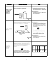
NOTE : If the Interlock Monitor Circuit operates and at the
same time the fuse blows with the Door opened,
be sure to replace the Control Circuit Board because
Relay 2 on the Control Circuit Board, the Door
Sensing Switch and the electric circuit related
on the Door Sensing Switch, which act as
Secondary Interlock Switch.
Test Procedures and Troubleshooting.................... 4
~
10
Disassembly Instructions ....................................... 11
~
14
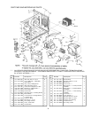
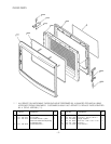
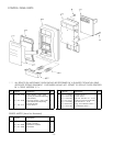
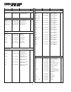
Exploded View and Parts List ................................ 15
~
20
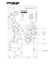
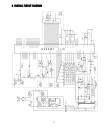
Overall Circuit Diagram .......................................... 21
Adjustment Procedures ................................................... 1
Specifications .................................................................. 2
Power Output Measurement ........................................... 2
Precautions and Repair Service Tips .............................. 2
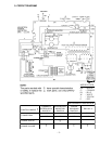
Circuit Diagram ............................................................... 3
1.1.
1.1.
1.
ADJUSTMENT PROCEDURESADJUSTMENT PROCEDURES
ADJUSTMENT PROCEDURESADJUSTMENT PROCEDURES
ADJUSTMENT PROCEDURES
TT
TT
T
O AO A
O AO A
O A
VOID POSSIBLE EXPOSURE TO MICROWVOID POSSIBLE EXPOSURE TO MICROW
VOID POSSIBLE EXPOSURE TO MICROWVOID POSSIBLE EXPOSURE TO MICROW
VOID POSSIBLE EXPOSURE TO MICROW
AA
AA
A
VEVE
VEVE
VE
ENERGY LEAKAGE, THE FOLLOWINGENERGY LEAKAGE, THE FOLLOWING
ENERGY LEAKAGE, THE FOLLOWINGENERGY LEAKAGE, THE FOLLOWING
ENERGY LEAKAGE, THE FOLLOWING
ADJUSTMENT OF THE INTERLOCK SWITCHESADJUSTMENT OF THE INTERLOCK SWITCHES
ADJUSTMENT OF THE INTERLOCK SWITCHESADJUSTMENT OF THE INTERLOCK SWITCHES
ADJUSTMENT OF THE INTERLOCK SWITCHES
SHOULD BE MADE ONLSHOULD BE MADE ONL
SHOULD BE MADE ONLSHOULD BE MADE ONL
SHOULD BE MADE ONL
Y BY AUTHORIZEDY BY AUTHORIZED
Y BY AUTHORIZEDY BY AUTHORIZED
Y BY AUTHORIZED
SERSER
SERSER
SER
VICE PERSONNEL.VICE PERSONNEL.
VICE PERSONNEL.VICE PERSONNEL.
VICE PERSONNEL.
The SANYO service center should have the designated
detector to measure the microwave energy leakage
after the repair or adjustment.
NOTENOTE
NOTENOTE
NOTE : Detector to be used at the service center is
NARDA 8100, 8200 or the equivalent.
PRIMARPRIMAR
PRIMARPRIMAR
PRIMAR
Y INTERLOCK SWITCH, INTERLOCKY INTERLOCK SWITCH, INTERLOCK
Y INTERLOCK SWITCH, INTERLOCKY INTERLOCK SWITCH, INTERLOCK
Y INTERLOCK SWITCH, INTERLOCK
MONITOR SWITCH AND DOOR SENSING SWITCHMONITOR SWITCH AND DOOR SENSING SWITCH
MONITOR SWITCH AND DOOR SENSING SWITCHMONITOR SWITCH AND DOOR SENSING SWITCH
MONITOR SWITCH AND DOOR SENSING SWITCH
ADJUSTMENTADJUSTMENT
ADJUSTMENTADJUSTMENT
ADJUSTMENT
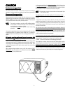
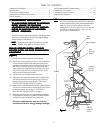
(Figure 1)(Figure 1)
(Figure 1)(Figure 1)
(Figure 1)
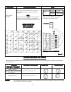
(1) Loosen 2 screws securing the Lever Stopper.
(2) Adjust the Lever Stopper position so that it is pushed
forward and pull backward until there is about zero
gap between the Latch Lever and the switch body on
the Primary Interlock Switch and at the same time
there is about zero gap between the Door Latch and
the switch body on the Door Sensing Switch when
the Door Latch is securely locked.
(3) Tighten the Lever Stopper screws securely.
(4) Make sure the Interlock Monitor Switch closes after
the Primary Interlock Switch opens when the Door
is opened very slowly, according to “CHECKOUT
PROCEDURE FOR SWITCHES” on page 6.
(5) Make sure the Interlock Monitor Switch opens before
the Primary Interlock Switch closes when the Door is
closed very slowly, according to “CHECKOUT
PROCEDURE FOR SWITCHES” on page 6.
(6) Make sure the microwave energy leakage should be
no greater than 4mW/cm
2
to allow for measurement
uncertainty when measured with a detector.
(All service adjustments must be made for
minimum microwave energy leakage readings.)
- TABLE OF CONTENTS -
Lever Stopper
Door
Sensing
Switch
Door
Latch
Interlock
Monitor
Switch
Primary
Interlock
Switch
Screws
Latch
Lever
Figure 1Figure 1
Figure 1Figure 1
Figure 1
- 1 -