


E.E.
E.E.
E.
REMOVING FUSEREMOVING FUSE
REMOVING FUSEREMOVING FUSE
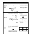
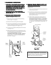
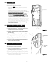
REMOVING FUSE
Remove the 20A Fuse with a screwdriver.
NOTENOTE
NOTENOTE
NOTE
-- When replacing the 20A Fuse, be sure to use an exact
repair part.
-- If the 20A Fuse blows immediately, check the Primary
Interlock Switch, the Relay 2 (on the Control Circuit Board)
and the Interlock Monitor Switch according to,
“CHECKOUT PROCEDURE“CHECKOUT PROCEDURE
“CHECKOUT PROCEDURE“CHECKOUT PROCEDURE
“CHECKOUT PROCEDURE
FOR SWITCHES”FOR SWITCHES”
FOR SWITCHES”FOR SWITCHES”
FOR SWITCHES” on page 6.
And make sure to check the microwave energy leakage
according to,
“1. ADJUSTMENT“1. ADJUSTMENT
“1. ADJUSTMENT“1. ADJUSTMENT
“1. ADJUSTMENT
PROCEDURES”PROCEDURES”
PROCEDURES”PROCEDURES”
PROCEDURES” on page
1, when the Primary Interlock Switch, the Relay 2 or the
Interlock Monitor Switch is adjusted or replaced.
-- If the Primary Interlock Switch, the Relay 2 and the Interlock
Monitor Switch operate properly, determine which of the
following is defective : Control Circuit Board, Blower Motor,
High Voltage Transformer, High Voltage Capacitor, High
Voltage Diode or Magnetron.
FF
FF
F
..
..
.
REMOVING CONTROL CIRCUIT BOARDREMOVING CONTROL CIRCUIT BOARD
REMOVING CONTROL CIRCUIT BOARDREMOVING CONTROL CIRCUIT BOARD
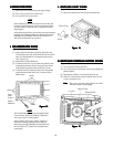
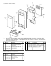
REMOVING CONTROL CIRCUIT BOARD
(See exploded view on page 18 and Figure 13)
(1) Remove the Connector S1, S102 and the Connector for
the Relay 2 from the Control Circuit Board.
(2) Remove 1 screw securing the Control Panel complete to
the Oven Cavity.
(3) Remove the FPC Connector from the Connector S101
while grasping up both lever ends of the plastic fastener.
(4) Remove 2 screws securing the Control Circuit Board to
the Control Base.
(5) Lift up the Control Circuit Board from its lower side and
take it out from the Control Base.
G.G.
G.G.
G.
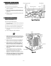
REMOVING TOUCH KEY BOARDREMOVING TOUCH KEY BOARD
REMOVING TOUCH KEY BOARDREMOVING TOUCH KEY BOARD
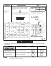
REMOVING TOUCH KEY BOARD
(Figure 14)
After removing the Control Circuit Board :
(1) Remove Control Base while lifting it up at the right side
and take it out from the Control Frame.
(2) Remove Control Sheet which is glued to Touch Key Board.
(3) Remove the Touch Key Board which is held on the Control
Base Bracket with the adhesive tape.
- 13 -
Control Frame
Control Sheet
Touch Key
Board
Figure 14Figure 14
Figure 14Figure 14
Figure 14
Figure 13Figure 13
Figure 13Figure 13
Figure 13
Control Frame
Control Base