


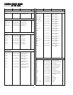

COMPONENTCOMPONENT
COMPONENTCOMPONENT
COMPONENT
CHECKOUT PROCEDURE CHECKOUT PROCEDURE
CHECKOUT PROCEDURE CHECKOUT PROCEDURE
CHECKOUT PROCEDURE
RESUL RESUL
RESUL RESUL
RESUL
TT
TT
T
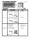
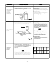
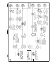
Measure the resistance : Across two terminals Normal reading :
with an Ohm-Meter on highest scale. Momentarily indicates several Ohms,
and gradually returns to 10 Meg-Ohms.
Abnormal reading :
Indicates continuity or 10 Meg-Ohms
from the beginning.
Measure the resistance : Across two terminals Normal reading :
with an Ohm-Meter on R x 10,000 scale. Indicates about the middle position in
one direction (forward direction) and
infinite Ohms in the reverse direction,
using meter which is provided with a
9 volt battery.
NOTENOTE
NOTENOTE
NOTE
- Some digital meter may show over
even in a forward direction because
low measuring voltage of meter does
not allow the meter current to pass
through the High Voltage Diode.
Abnormal reading :
Indicates continuity or infinite Ohms
in both directions.
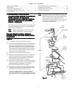
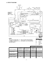
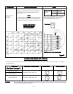
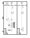
Measure the voltage : Between test point TP-1,
TP-2, TP-3 or TP-4 and Ground between TP-5
and TP-6 (See Control Circuit Board on
page 19).
NOTENOTE
NOTENOTE
NOTE
- Proceed with the check of the Step-Down
Transformer, to see if any one of the measured
values is different from the specified values.
Figure 8Figure 8
Figure 8Figure 8
Figure 8
Ohm-MeterOhm-Meter
Ohm-MeterOhm-Meter
Ohm-Meter
Figure 7Figure 7
Figure 7Figure 7
Figure 7
Ohm-MeterOhm-Meter
Ohm-MeterOhm-Meter
Ohm-Meter
- 5 -
Test TP-5 /
Point
TP-1 TP-2 TP-3 TP-4
TP-6
Voltage
-5V -15V -25V -36V 2.0V
DC DC DC DC AC
CONTROL
CIRCUIT
BOARD
HIGH-VOLTAGE
DIODE
HIGH-VOLTAGE
CAPACITOR
including
BLEEDER
RESISTOR