


17
PLANNING
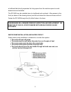
1. Keep tube runs as short as possible. The suction (return) line should be as direct
as possible with a minimum number of bends.
2. Tape the 1/4" line and the 1/2" line together in the section between the V/U and
the DC 5000. This is for thermal exchange (sub cooling).
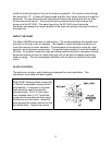
POSITIONING THE RFD
• The RFD is fitted with a sight glass. This glass must be visible for charging
and servicing the system. It can be viewed from the top at up to a 45-degree
angle but not from the bottom or side. A mirror installed above the glass is one
way of saving a poorly planned installation. Avoid this if possible. Be sure the
sight glass is easily visible!
• Observe the inlet/outlet on RFD when mounting it. The glass is offset toward the
outlet.
• The RFD should be unpacked and installed only after all the lines are run and all
other fittings are made.
HELPFUL TOOLS
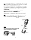
• Coil spring-type tube benders are available for 3/8"-1/2" O.D. tube. These springs
are slid over the tube. The bend is formed in the spring, and then the spring is
removed by unscrewing.
• Lever benders for each size tube. Lever benders will make the tightest possible
bend without distorting the tube.
• Mini tube cutter: "IMP" by Gould Imperial requires less than 1 1/2" radius
clearance for the cut. This is essential to trim the plate tubes.
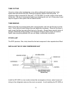
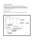
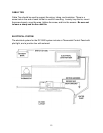
LINE CONNECTION PLAN
Run 1/4" copper tube from the DC 5000 to the RFD. From the RFD 1/4" copper tube
continues to the V/U. Run 1/2" copper tube from the large connection on the V/U to the
DC 5000. The two lines should be combined with tape and insulated together. See
Insulating the Lines.