25
GAUGES
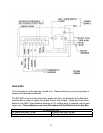
Gauges must be used in the evacuation and charging. They will provide information on
the operation of the system when troubleshooting.
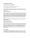
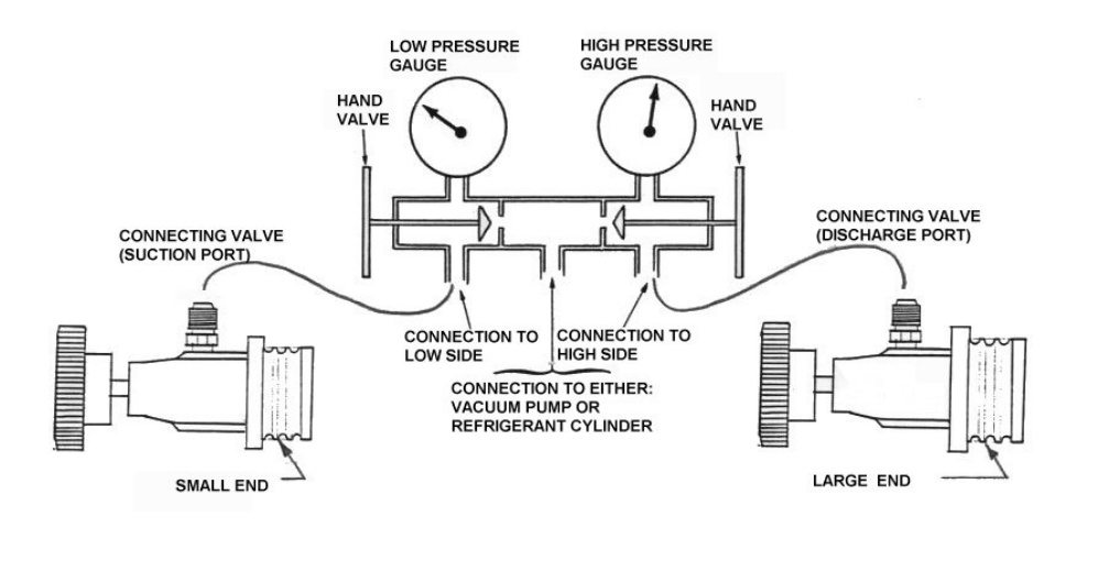
A gauge sets consist of two gauges installed in a manifold with two hand wheel valves
and hoses to connect the gauges to the system. The left gauge (blue) is a compound
device; it indicates pressure and also vacuum. The right gauge (red) indicates pressure
only. The hand wheels open a center port (yellow) to the left or right side respectively.
Operation of the hand wheels is only necessary when moving refrigerant or evacuating.
With the hand wheels closed, the gauges read the pressures of the connection points.
At the end of the red and blue service hoses are R-134a connecting valves. At the end
of the yellow hose is a self-sealing check valve that will only open when attached to a
fitting.
Keep your gauges clean. Inspect the rubber gaskets and "o" rings on the hose ends.
Leak-check the gauge valve packing and all hose connections. Check and reset the
"O" (zero) on the low side gauge while open to atmospheric pressure, if necessary.
R-134a SERVICE CONNECTING VALVES
The R-134a connecting valves on the gauge hose ends are quick connect fittings with a
specially designed valve that when turned opens and closes the hose end while
opening and closing the access service port.


