


PREPARATION
Remove all tape and packaging. Remove clear plastic
film that covers some parts (around glass oven doors,
side trim) and any tape or packaging from inside the
oven,
Remove the accessory pack from the oven.
Check to see if any range parts have come loose during
shipping.
ELECTRICAL REQUIREMENTS
This appliance must be supplied with the proper voltage
and frequency, and connected to an Individual, properly
grounded branch circuit, protected by a circuit breaker or
time delay fuse, as noted on raUng plate.
Wiring must conform to National Electrical Cedes. Ifthe
electric service provided does not meet the above
specitlcatlons, call a licensed electrician.
You can get a copy of the National Electrical Code, ANSI/
NFPA No. 70-Lstest Edition by writing:
National Fire Protection Association
Battery March Park
Quincy, MA 02269
Effective January 1, 1996, the National Electrical Code
requires that new or rewired construction utilize a four-
conductor connection to anelectric range. When installing
an electric range In a new construction, follow the
instructions In NEW CONSTRUCTION AND FOUR-
CONDUCTOR BRANCH CIRCUIT CONNECTION.
ifyou fail to wire you r range inaccordance with governing
codes, you may create a hazardous condition.
You must use a three-wire, single-phase AC 120/240 Volt
or 208Y/120 Volt, 60 Hertz electrical system to operate
your range.
Use #8 gauge wire and 40 Amp fuse or circuit breaker for
120/240 Volt and 208Y/120 Volt systems.
The range connector block Is approved for copper wire
connection only. If you are connecting to aluminum
house wiring, you must use special UL approved
connectors for joining copper to aluminum.
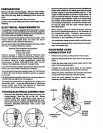
TO MAKE ELECTRICALCONNECTION:
Remove the junction block access cover (on
range back). See Fig. 4A or Fig. 4B. Some
models will have a one.piece wire cover as
shown in Fig. 4B. When reinstalling the one-
piece wire cover_ make sure that wire does not
become pinched between wire cover and
mainback.
Allnewconstmctions, mobile homes and Installations
where local codes do not allow grounding through
neutral, require a four-wire flexible cord kit. If the
range is rated between 8,750 and 16,500 watts, the
cord kit must be rated for 40 amps-125/250 volts. If
the range Is rated between 16,501 and 22,500 watts
the cord kit must be rated for 50 amps-125/250 volts.
For existing construction, a thrse-wlre flexible cord
kit may be used, and the same ratings apply as
described above.
When using a cord kit rated 40 Amps, remove
the next to outermost knockout (1 3/8" diameter) In
the connection plate. Likewise, when using a
cord kit rated 50 Amps, remove the outermost
knockout (1 3/4" diameter) In the plate.
You must use a clamp or strain relief to hold thecord.
Terminations must beeit her closed loop terminals or
open end spade lugs.
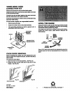
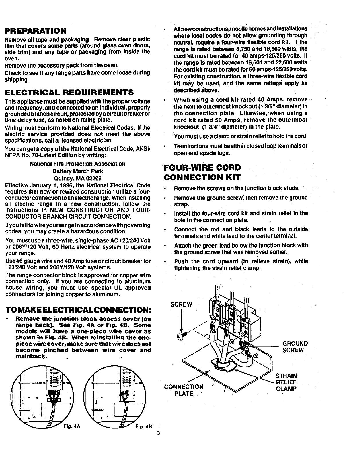
FOUR-WIRE CORD
CONNECTION KIT
Remove the screws on the junction bloc k studs.
Remove the ground screw, then remove the ground
strap.
Install the tour-wire cord kit and strain rellet In the
hole In the connection plate.
Connect the red and black leads to the outside
terminals and white lead to the center terminal.
Attach the green lead below the junction block with
the ground screw that was removed earlier.
Push the cord upward (to relieve strain), while
tightening the strain rellet clamp.
SCREW
GROUND
SCREW
CONNEC_ON
PLATE
STRAIN
RELIEF
CLAMP
Fig. 4A Fig. 4B
3