


4
INSTALLATION MANUAL
INSTALLATION
• Review and plan ahead all safety instructions, cabinet
clearances and dimensions, power supply placement and
electrical requirements before installing.
• Proper installation is the responsibility of the installer and
product failure due to improper installation is not covered by
warranty.
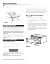
Note: This appliance must be properly grounded
Attention Installer: This appliance must be hard wired (direct
wired) into an approved junction box. A plug and receptacle is
NOT permitted on this product.
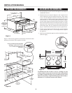
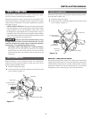
A SELECTING 208 OR 240 VOLT CONNECTION
This appliance can be set for 208V or 240V. The voltage setting for
your appliance is pre-set at 240V from the factory. Follow these
steps to change the voltage setting.
1 Locate the voltage switch on the left side of the appliance
(facing the front). See Figure 4.
2 Remove the screw and rotate the switch plate 180˚ as indicated
in the Figure 5.
3 Reinsert the switch plate and replace screw as indicated
in Figure 6. The voltage setting is indicated by the visible
marking.
180˚
240V
208V
Screw
Screw
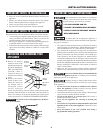
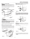
B ADJUSTING ANTI-TIP BRACKET
Measure the thickness of the counter. See Figure 7. Locate the
Anti-Tip Bracket on the backside of the appliance. See Figure 8.
Loosen screws and adjust space between the glass cooktop and
bracket to match the counter thickness plus 1/16”. See Figure 9.
Tighten the screws to secure the bracket at the correct counter height
dimension.
Measure
thickness
Back of unit
Anti-Tip bracket
Loosen screws to adjust
Countertop
thickness +1/16"
from bottom of
cooktop glass bracket
to top of Anti-Tip bracket
Figure 4
Figure 5
Figure 7
Figure 8
Figure 6
Figure 9