


5
INSTALLATION MANUAL
PoWER CoRD ConnECtIons
4-WIRE CONNECTION INSTRUCTIONS
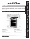
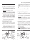
Before wiring the range, review the suggested power source location
drawing in Figure 2. If connecting to a 4-wire electrical system for a
new branch-circuit or mobile home use a 4-wire connection.
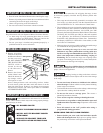
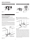
1 Follow the power supply cord kit manufacturer’s Installation
Instructions and install the strain relief clamp on the cord. See
Figure 8.
2 Connect the end connectors for line 1, line 2 and neutral and
tighten securely to the terminal block. See Figure 9.
IMPORTANT
DO NOT LOOSEN the factory installed nut
connections which secure the range wiring to the terminal
block. Electrical failure or loss of electrical connection may
occur if these 3 nuts are loosened or removed.
3 You must disconnect the ground strap. Remove the factory
installed ground screw and plate to release the copper ground
strap from the frame of the range. Cut and discard the copper
ground strap and plate. KEEP the ground screw. See Figure 9.
4 Connect the green ground wire lead with the eyelet to the frame
of the range with the ground screw using the same hole in the
frame where the ground screw was originally installed. See
Figure 9.
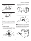
5 Make sure all screws are tightened securely and replace the
rear access cover and secure with screw. See Figure 7.
3-WIRE CONNECTION INSTRUCTIONS
For existing installations ONLY, refer to Figure 10.
1 Follow the power supply cord kit manufacturer’s Installation
Instructions and install the strain relief clamp. See Figure 10.
2 Connect the end connectors for line 1, line 2 and neutral and
tighten securely to the terminal block. See Figure 10.
IMPORTANT
DO NOT LOOSEN the factory installed nut
connections which secure the range wiring to the terminal
block. Electrical failure or loss of electrical connection may
occur if these 3 nuts are loosened or removed.
3 A ground strap is installed on this range which connects the
center terminal of the neutral terminal block to the range
chassis. The ground strap is connected to the range by the
center, lowest screw. See Figure 10. The ground strap must
not be removed unless National, State or Local Codes do not
permit use of a ground strap.
NOTE:
If the ground strap is removed for any reason, a
separate ground wire must be connected to the separate ground
screw attached to the range chassis and to an adequate ground
source.
4 Make sure all connections are tightened securely and replace
the rear access cover and secure with screw. See Figure 7.
3 & 4-WIRE PERMANENT WIRE CONNECTIONS
3–wire permanent connection – follow steps 1, 2 and 5 below.
4–wire permanent connection – follow all steps below.
Before wiring the range, review the suggested power source location
drawings in Figure 2. If connecting to a 4-wire electrical system:
1 Follow the manufacturer’s Installation Instructions for installing
the strain relief clamp.
2 Strip insulation away from the ends of the permanent wiring
for line 1, line 2 and neutral; also strip ground wire on 4-wire
connections. Tighten all 3 or 4-wire leads to the terminal block.
Follow wire locations shown in Figure 11.
IMPORTANT
DO NOT LOOSEN the factory installed nut
connections which secure the range wiring to the terminal
block. Electrical failure or loss of electrical connection may
occur if these 3 nuts are loosened or removed.
NOTE:
For 3-wire permanent connection skip steps 3 and 4
and continue with step 5.
3 Disconnect the ground strap. Remove the factory installed
ground screw and plate to release the factory installed copper
ground strap from frame of the range. Cut and discard the
copper strap from the terminal block. KEEP the ground screw,
ground plate and go to step 4.
4 Connect the green ground wire lead to the frame of the range
using the ground screw and plate as shown in Figure 12. Be sure
to install using the same hole in the frame where the ground
screw was originally installed.
5 Make sure all connections are tightened securely and replace
the rear access cover. See Figure 7.
NOTE:
Non-terminated eld wire compression connections
must be set at approximately 90 in./lb.
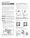
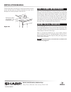
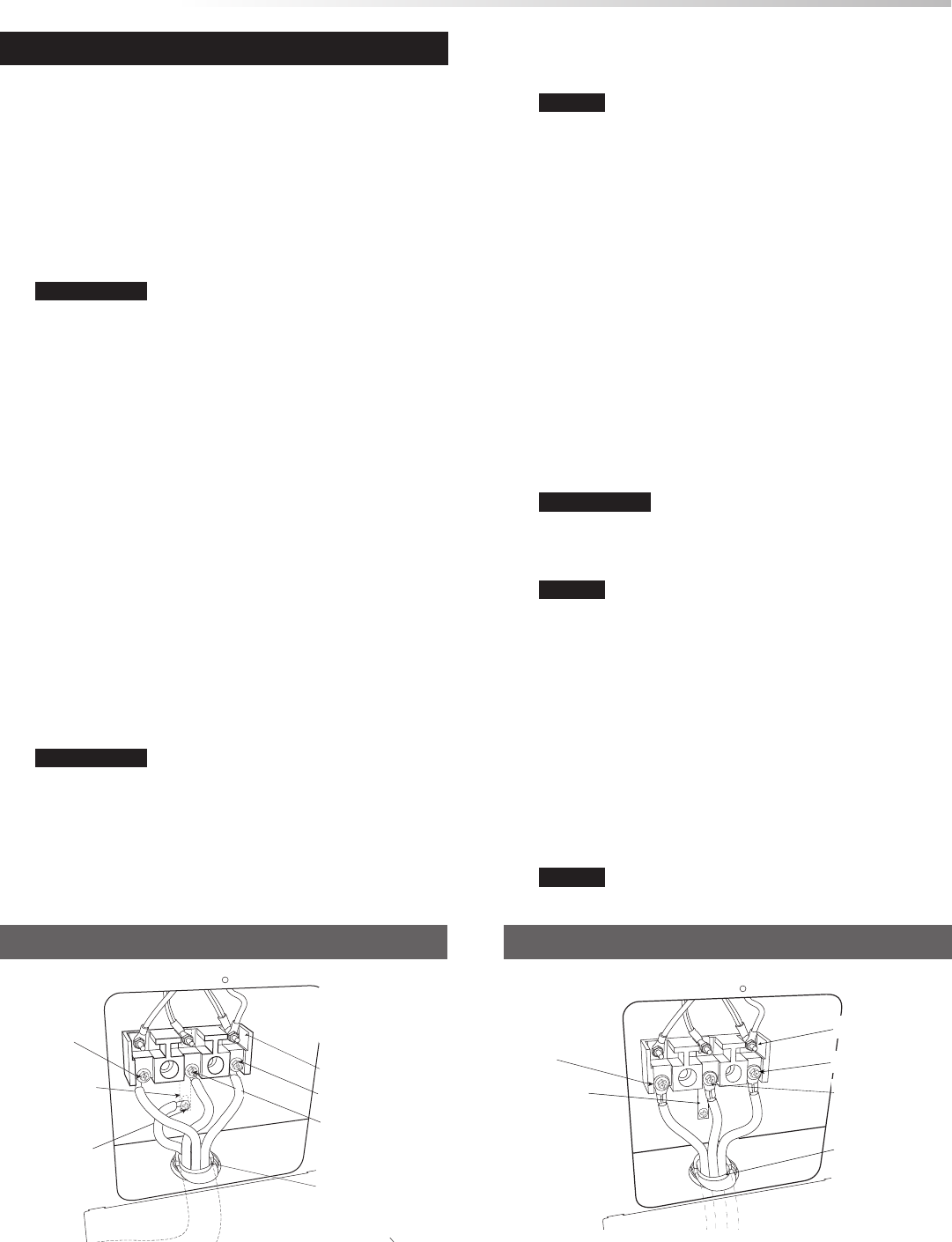
4-WIRE CONNECTION
Terminal block
w
h
i
t
e
g
r
e
e
n
Connect green
insulated copper
ground wire with
ground screw here.
Cut ground strap.
Discard ground
strap and ground
plate.
Connect neutral
(white or center) here.
Connect
line 1 here.
Connect line 2 here.
b
l
a
c
k
Note: I
nstall strain
relief clamp. Center
or white wire must
always be attached to
the center terminal on
block.
A user supplied strain
relief clamp must be
installed at this
location. It requires 1
3
/8" (3.5 cm) diameter
cord kit hole.
r
e
d
Figure 9
3-WIRE CONNECTION
Figure 10
G
ro
u
n
d st
ra
p
T
e
rmi
n
a
l b
l
o
ck
Note: Install strain
relief clamp. Center
must always be
attached to the
center terminal on
block.
Connect neutral
here.
Connect line
1 here.
Connect line 2 here.
A user supplied
strain relief clamp
must be installed
at this location. It
requires 1
3
/8"
(3.5 cm) diameter
cord kit hole.