


7
INSTALLATION MANUAL
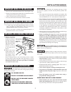
b DRILL PILOT HOLES AND FASTEN BRACKET
Drill a
1
/8-inch pilot hole where screws are to be located. If bracket
is to be mounted to the wall, drill pilot hole at an approximate 20
degree downward angle. If bracket is to be mounted to masonry or
ceramic oors, drill a
5
/32-inch pilot hole 1
3
/4-inches deep. The
screws provided may be used in wood or concrete material. Use a
5
/16-inch nut-driver or at head screwdriver to secure the bracket
in place.
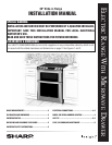
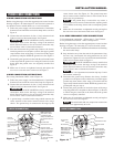
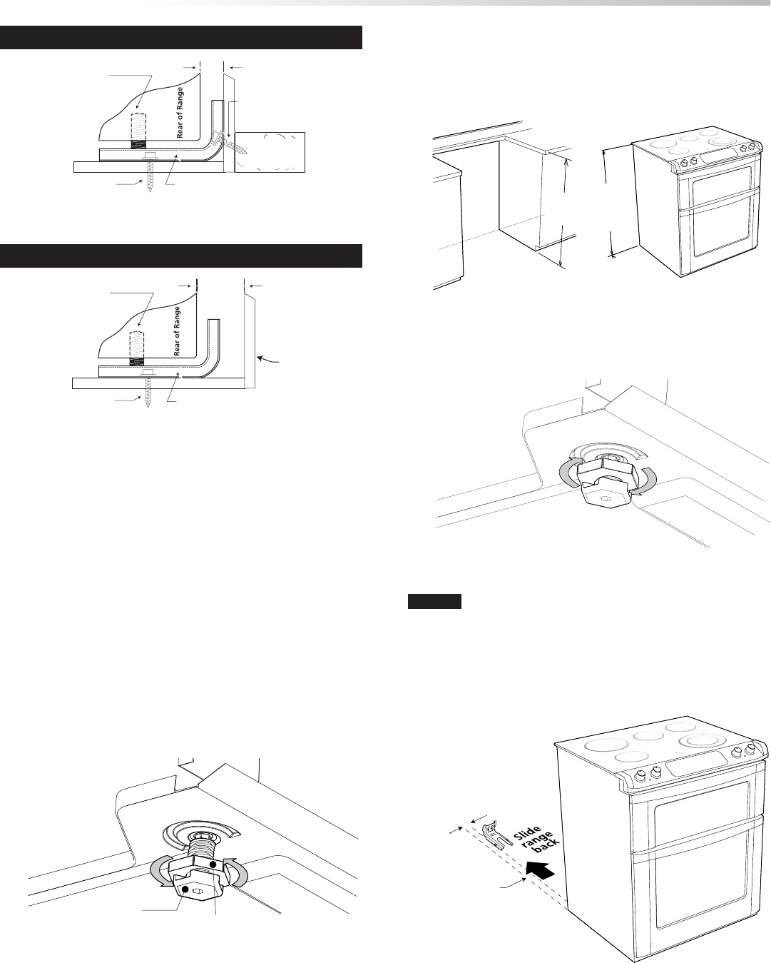
c LEVEL AND POSITION RANGE
• Measure from the countertop to the oor height to determine
the height that the back of the range needs to be set at.
• Loosen legs and lock nuts to set level of the range. (Note that
the lock nuts are only on the rear feet). See Figure 16.
Figure 19
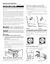
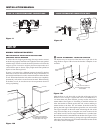
FASTEN BRACKET (WALL OR FLOOR MOUNTING)
FASTEN BRACKET (FLOOR MOUNTING ONLY)
floor mount
floor mount
Anti-Tip bracket
Anti-Tip bracket
wall
wall mount
wall plate
more than
1
1
/4"
max 1
1
/4"
leveling leg
leveling leg
Figure 14
Figure 15
Range Leg
Lock Nut
(Rear leg only)
Figure 16
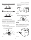
• Adjust the back leveling legs with an adjustable wrench or pliers.
Measure from the oor to the bottom of the cooktop glass (X)
and adjust the legs to match the measurement (Y) taken from
the cutout. See Figure 17.
(X")
floor to bottom
off cooktop
glass
(Y")
floor to top
of countertop
Figure 17
• After leveling, tighten the lock nuts on the rear to prevent the
feet from turning when sliding into position. See Figure 18.
Figure 18
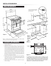
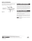
NOTE:
A minimum clearance of
1
/8-inch is required between
the bottom of the range and the leveling leg to allow room for the
bracket. Use a level to check your adjustments. Plug range into
properly prepared electrical receptacle or if hard wired, check that
it was completed properly. Check oor condition for evenness and
stability. Slide range back into position. See Figure 19.
Range Slide
1
5
/8" to edge
of bracket