


6
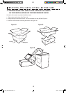
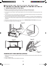
Open the bottom of the carton, bend the carton flaps back and tilt the oven
over to rest on plasticfoam pad. Lift carton off oven and remove all packing
materials, WALL and TOP CABINET TEMPLATE, Turntable, and Turntable
Support. SAVE THE CARTON AS IT MAY MAKE INSTALLATION EASIER.
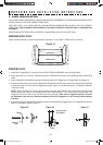
1. Remove the feature sticker from the outside of the door, if there is one.
2. DO NOT REMOVE THE WAVEGUIDE COVER, which is located on the
right side wall of the oven cavity. Check to see that there is a WALL TEM-
PLATE and TOP CABINET TEMPLATE. Read enclosures and SAVE the
Operation Manual.
Check the oven for any damage, such as misaligned or bent door, damaged door seals and sealing surfaces,
broken or loose door hinges and latches and dents inside the cavity or on the door. If there is any damage, do not
operate the oven and contact your dealer or SHARP AUTHORIZED SERVICER. See Installation Instructions for
more details.
U N P A C K I N G A N D I N S T A L L A T I O N I N S T R U C T I O N S
INSTALLATION INSTRUCTION
Please read all instructions thoroughly before installing the Over the Range Microwave Oven/Hood
System. Two people are recommended to install this product.
If a new electrical outlet is required, its installation should be completed by a qualified electrician
before the Microwave Oven/Hood is installed. See 3 ELECTRICAL GROUNDING INSTRUCTIONS on
page 7.
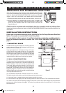
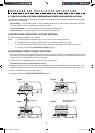
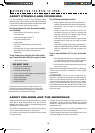
1 MOUNTING SPACE
This Microwave Oven/Hood requires a mounting space on
a wall as shown in Figure 1. It is designed to be used with
standard 12-inch wall cabinets.
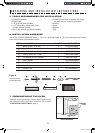
If the space between the wall cabinets is 36 or 42 inches,
a Filler Panel Kit can be used to fill the gap. The metal filler
panels come in 3-inch wide pairs. One set is needed for a
36-inch opening and 2 sets for a 42-inch opening. See page
14 for ordering information. The Filler Panel Kit should be
installed before the Microwave Oven/Hood is installed.
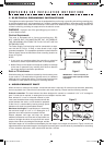
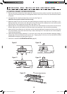
2 WALL CONSTRUCTION
This Microwave Oven/Hood should be mounted against and
supported by a flat vertical wall. The wall must be flat for
proper installation. If the wall is not flat, use spacers to fill
in the gaps. Wall construction should be a minimum of
2” x 4” wood studding and 3/8” or more thick dry wall or
plaster/lath. The mounting surfaces must be capable of
supporting weight of 110 pounds—the oven and contents—
AND the weight of all items which would normally be stored
in the top cabinet above the unit.
The unit should be attached to a minimum of one 2” x 4” wall stud.
To find the location of the studs, one of the following methods may be used:
A. Use a stud finder, a magnetic device which locates the nails in the stud.
B. Use a hammer to tap lightly across the mounting surface to find a solid sound. This will indicate stud location.
The center of the stud can be located by probing the wall with a small nail to find the edges of the stud and then
placing a mark halfway between the edges. The center of any adjacent studs will normally be 16” or 24” to either
side of this mark.
UNPACKING AND EXAMINING YOUR OVEN
Backsplash
At least 2"
66" or more
from floor
15.5"
30"
12"
30" or more from
cooking surface
Figure 1
318-3_1405,06 manual.indd 6 5/14/07 2:13:59 PM