


7
U N P A C K I N G A N D I N S T A L L A T I O N I N S T R U C T I O N S
3 ELECTRICAL GROUNDING INSTRUCTIONS
This appliance must be grounded. This oven is equipped with a cord having a grounding wire with a grounding plug.
It must be plugged into a wall receptacle that is properly installed and grounded in accordance with the National
Electrical Code and local codes and ordinances. In the event of an electrical short circuit, grounding reduces risk
of electric shock by providing an escape wire for the electric current.
WARNING - Improper use of the grounding plug can result in
a risk of electric shock.
Electrical Requirements
The oven is equipped with a 3-prong grounding plug. DO
NOT UNDER ANY CIRCUMSTANCES CUT OR REMOVE
THE GROUNDING PIN FROM THE PLUG. DO NOT USE AN
EXTENSION CORD.
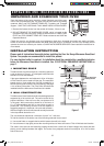
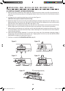
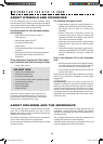
The Power Supply Cord and plug must be connected to a sepa-
rate 120 Volt AC, 60 Hz, 15 Amp, or more branch circuit, single
grounded receptacle. The receptacle should be located inside the
cabinet directly above the Microwave Oven mounting location as
shown in Figure 2.
NOTE:
1. If you have any questions about the grounding or electrical
instructions, consult a qualified electrician or serviceperson.
2. Neither Sharp nor the dealer can accept any liability for damage
to the oven or personal injury resulting from failure to observe
the correct electrical connection procedures.
Radio or TV Interference
Should there be any interference caused by the microwave oven
to your radio or TV, check that the microwave oven is on a different
electrical circuit, relocate the radio or TV as far away from the oven
as feasible or check position and signal of receiving antenna.
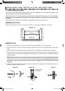
4 HOOD EXHAUST DUCT
When the hood is vented to the outside, a hood exhaust duct is required. All ductwork must be metal; absolutely
do not use plastic duct. Check that all connections are made securely. Please read the following carefully:
Exhaust connection: The hood exhaust has been designed to connect to a standard 3-1/4” x 10” rectangular
duct. If round duct is required, a rectangular-to-round adapter must be used.
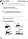
Rear exhaust: If a rear or horizontal exhaust is to be
used, care should be taken to align the exhaust with the
space between the studs, or wall should be prepared
at the time it is constructed by leaving enough space
between wall studs to accommodate exhaust.
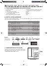
Maximum duct length: For satisfactory air movement,
the total duct length of 3-1/4” x 10” rectangular or 6”
diameter round duct should not exceed 140 feet.
Elbows, adapters, wall caps, roof caps, etc. present
additional resistance to air flow and are equivalent to a
section of straight duct which is longer than their actual
physical size. When calculating the total length, add the
equivalent lengths of all transitions and adapters plus the length of all straight duct sections. Figure 3 shows the
approximate feet of equivalent length of some typical ductwork parts. Use the values in parentheses for calculating
air flow resistance equivalent, which should total less than 140 feet.
Figure 2
Grounded
Receptacle
Opening for
Power Cord*
Figure 3
IMPORTANT: * Power cord opening for
metal cabinets: Deburr opening to remove
rough edges.
318-3_1405,06 manual.indd 7 5/14/07 2:13:59 PM