


7
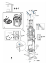
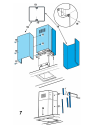
Installation ceiling model (Island)
Fig. 5-6-7
1. Adjust the extension of the support structure of the hood.
The final height of the hood depends on this adjustment.
Note: In some cases the upper section of the trellis is
fixed to the lower section with 1 or more screws, possibly
check and remove them temporarily to allow adjusting
the support structure.
2. Fix the two sections of the structure with a total of 16
screws (4 per corner).
Apply 1 or 2 brackets on the upper section for extensions
superior to the minimum (on the basis of what has been
envisaged as equipment) to reinforce it.
Note: 1 bracket can already be temporarily fixed with two
screws to the trellis for transporting, possibly moving it
into the desired position or finish its fixing with 6 added
screws
To do this:
a. Enlarge the brackets to be fixed slightly to be able to
apply them to the exterior of the structure.
b. Position the reinforcement bracket immediately over
the fixing point of the two sections with a total of 8 screws
(2 per corner).
If supplied, fix the second bracket in an equidistant
position between the first reinforcement bracket and the
upper side of the trellis, fixing with 8 screws (2 per
corner).
Note: in positioning and fixing the reinforcement
bracket(s) check that these do not impede easy fixing of
the discharge tube (aspiration version) or the deflector
(filtering version).
3. Apply the perforation diagram of the ceiling on the
vertical of the cooking top (the centre of the scheme must
correspond to the centre of the cooking top and the sides
must be parallel to the sides of the cooking top – the side
of the scheme with the word FRONT corresponds to the
control panel side). Connect the electricity.
4. Make holes as indicated (6 holes for 6 wall dowels – 4
dowels for the hook), screw 4 screws into the external
holes leaving a space between the head of the screw and
the ceiling of about 1cm.
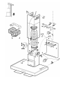
5. Introduce a discharge tube into the trellis and connect to
the connection ring of the motor space (discharge tube
and fixing band not supplied). The discharge tube must
be sufficiently long to reach the outside (aspiration
version) or the deflector (filtering version).
6. Only for filtering version: mount deflector F on the
trellis and fix it with 4 screws to the apposite bracket and,
finally, connect the discharge tube to the connection ring
on the deflector.
7. Hook the trellis to the ceiling with the 4 screws (see
operation 4).
8. Screw the 4 screws up with decision.
9. Introduce and screw another two screws up decisively
into the holes for safety fixing remaining free.
10. Connect the electricity to the domestic power. The
electricity supply must be connected only after installation
has been completed.
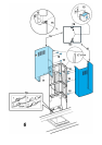
11. Insert 2 pegs at the sides of the fixing points between the
trellis and the hood.
12. Hook the hood to the trellis, check the perfect hooking –
to hook the hood to the trellis screw 4 screws up partially.
ATTENTION! The side of the trellis with the connection
box corresponds to the side of the control panel once the
hood is mounted.
13. Fix the hood to the trellis with two screws that will also
serve to centre the two parts.
14. Screw the 4 screws that fix the trellis to the hood up with
decision.
15. Apply the nuts supplied with fixing hooks inside the
sections of the upper and lower flues in correspondence
with the rectangular slots. A total of 14 nuts must be
mounted.
16. Couple the two upper sections of the hood to cover the
trellis so that the slits on the sections are positioned, one
on the same side as the command panel and the other
on the opposite side.
Screw the two sections up with 8 screws (4 per side –
also see the diagram plan for the coupling of the two
sections).
17. Fix the entire upper flue to the trellis near the ceiling with
two screws (one per side).
18. Connect the electricity of the command panel and the
bulbs.
19. Couple the two lower sections of the hood to cover the
trellis, using 6 screws (3 per side; also see the diagram
plan for the coupling of the two sections).
20. Insert the lower section into the apposite housing to
completely cover the motor space and the electricity
connections box.
21. Apply 2 ribbons (supplied as kit) to cover the fixing points
of the lower sections of the hood. (ATTENTION! THE
RIBBONS FOR THE LOWER HOOD ARE
RECOGNISABLE BECAUSE THEY ARE NARROWER
AND LESS DEEP).
The wider and deeper ribbons are those used for the
upper hood and are to be cut to measure.
22. Mount the carbon filter and the fat(s) filter/s) frame again
and switch the electric supply on using the central electric
panel and check the correct functioning of the hood.
Installation wall model
Fig. 8
1. Using a pencil, draw a line on the wall, extending up to
the ceiling, to mark the centre. This will facilitate
installation.
2. Rest the drilling template against the wall: the vertical
centre line printed on the drilling template must
correspond to the centre line drawn on the wall, and the
bottom edge of the drilling template must correspond to
the bottom edge of the hood.
3. Place the lower support bracket on the perforation
diagram making it coincide with the traced triangle, mark
the two external holes and perforate. Remove the
perforation diagram, insert two wall-dowels and fix the
support bracket of the hood with two 5x45 mm screws.
4. Hang the hood onto the lower bracket.
5. Adjust the distance of the hood from the wall.
6. Adjust the horizontal position of the hood.