


SERVICE 4FR-45 RESTAURANT RANGE FRYER
PAGE 22 OPERATOR’S MANUAL 1182128
SERVICE
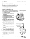
Checking and Adjusting Auto Safety Pilot
The pilot flame should surround the thermopile for 1/2". It must be large and sharp enough to cause the
thermopile to glow a dull red, or sufficient to hold the safety valve open.
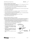
1. Remove pilot flow adjustment cap screw (see diagram below).
2. Adjust pilot key to provide properly sized flame.
3. Replace pilot adjustment cap screw.
Converting from Natural Gas to LP Gas
Obtain a natural-to-LP gas conversion kit (part number 4440499) from your authorized Southbend parts
distributor. The kit comes with five LP gas orifice spuds, of which four are used. In the following procedure,
refer to the parts diagram on page 28 and the figures below on the right.
1. Turn off gas supply to the fryer.
2. Remove the existing natural gas spud from each
burner and replace it with an LP gas spud from
the conversion kit.
3. Loosen the compression fitting at the pilot and
remove the pilot tubing from the pilot.
4. Remove the two pilot mounting screws.
5. Remove the natural gas pilot orifice from the pilot
and replace it with the LP gas pilot orifice from
the conversion kit.
6. Remount the pilot assembly, reposition the pilot
tubing, and tighten the compression fitting.
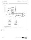
7. Partially depress and turn the manual gas control
knob on the combination gas valve to “OFF” (see
diagram at right).
8. Remove pressure regulator adjustment cap
screw and pressure regulating adjustment screw.
9. Remove the existing spring.
10. Insert the replacement spring with the tapered
end down.
11. Install new plastic pressure regulating adjustment
screw. Ensure that the screw top is flush with the
regulator top.
12. Turn the pressure regulator adjustment scre
w
clockwise six complete turns. The preliminary
pressure setting will then be approximately 10"
W.C. for the LP gas.
13. Turn on the gas supply to the fryer. With the
main burners on, test for leaks using a soap
solution.
14. Check and adjust the pressure regulator (see
procedure on page 21). The pressure should be
10" W.C. for LP gas.
15. Install the new cap screw.
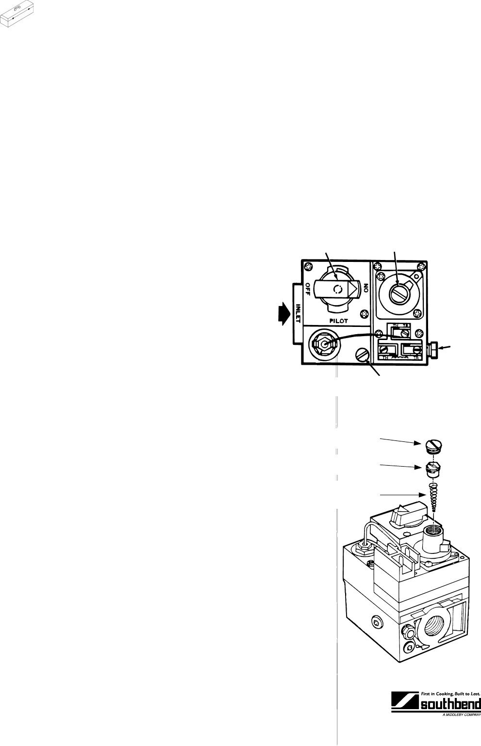
Pilot
Gas
Outlet
Pilot Flow Adjustment
Screw (below cap screw)
Gas
Inlet
Manual Gas
Control Knob
Pressure Regulato
r
Adjustment
(below cap screw)
Cap Screw (black for LP
gas, silver for natural gas)
Pressure Regulating
Adjustment Screw (white)
Spring (tapered end down,
red for LP gas, stainless
steel for natural gas)