


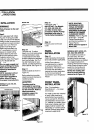
INSTALLATION
INSTRUCTIONS
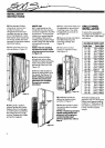
IAwARNING I
Toreduce the possibility of
the unit tipping forward,
you must reposition the
front levelers to make
contact with the floor. You
will have to extend these
legs when the unit is finally
positioned.
Step 6
Remove all packing materials
and tape.
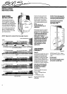
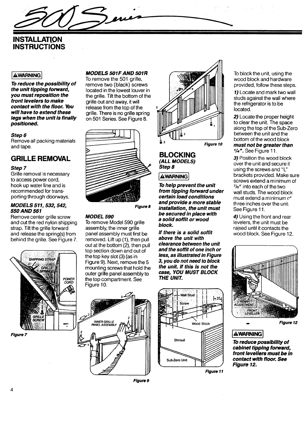
GRILLE REMOVAL
Step 7
Grille removal is necessary
to access power cord,
hook up water line and is
recommended for trans-
porting through doorways.
MODELS 511, 532, 542,
550 AND 561
Remove center grille screw
and cut the red nylon shipping
strap. Tilt the grille forward
and release the spring(s) from
behind the grille. See Figure 7.
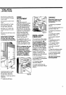
MODELS 501F AND 501R
To remove the 501 grille,
remove two (black) screws
located in the lowest louver in
the grille. Tilt the bottom of the
grille out and away, it will
release from the top of the
grille. There is no grille spring
on 501 Series. See Figure 8.
Figure 8
MODEL 590
Toremove Model 590 grille
assembly, the inner grille
panel assembly must first be
removed. Lift up (1), then pull
out at the bottom (2), then pull
top section down and out of
the top key slot (3) (as in
Figure 9). Next, remove the 5
mounting screws that hold the
outer grille panel assembly to
the top compartment. See
Figure 10.
Figure 10
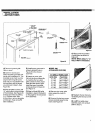
BLOCKING
(ALL MODELS)
Step 8
I"WARN'NGI
Tohelp prevent the unit
from tipping forward under
certain load conditions
and provide a more stable
installation, the unit must
be secured in place with
a solid soffit or wood
block.
ff there is a solid soffit
above the unit with
clearance between the unit
and the soffit of one inch or
less, as illustrated in Figure
3, you do not need toblock
the unit. If this is not the
case, YOU MUST BLOCK
THE UNIT.
Toblock the unit, using the
wood block and hardware
provided, follow these steps.
1) Locate and mark two wall
studs against the wall where
the refrigerator isto be
located.
2) Locate the proper height
to clear the unit. The space
along the top of the Sub-Zero
between the unit and the
bottom of the wood block
must not be greater than
1/4_.See Figure 11.
3) Position the wood block
over the unit and secure it
using the screws and "1"
brackets provided. Make sure
screws extend a minimum of
71_,into each of the two
wall studs. The wood block
must extend a minimum e'
three inches over the unit
See Figure 11.
4) Using the front and rear
levelers, the unit must be
raised until itcontacts the
Wood block. See Figure 12.
Figure 7
4
Figure 9
Figure 11
Figure 12
tAWARNINGI
Toreduce possibility of
cabinet tipping forward,
front levellers must be in
contact with floor. See
Figure 12.