


t '° TALLATION
,.. TRUCTIONS
iSTALLATION
_WARNING ]
;hut-off power to the wall
)utlet.
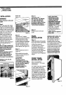
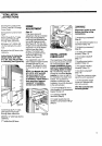
;tep 9
Jnit isequipped with rollers.
)luginto 15 amp grounded
)utletand roll unit into desired
)osition under the wood block
)rsoffit and connect icemaker
rater line to unit. Remove
]a}den hose fitting from
)lastic bag and attach the
14" compression nut and
;leeveon copper tubing
)efore attaching the hose
itting to the solenoid valve.
=urge line before final
lookup to valve. See Figure
13,ForModel 590 see
_14.
,ion water supply and
:heck all fittings for leaks.
;fake certain electrical
_arness is attached to
;olenoid.
_iOTE: Icemaker will not
immediately fill with
_/ater when supplied to
valve. Allow 24 hours
_orproper ice production.
•ODELS 511, 532, 542, 550,
;61 AND 501F
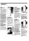
SOLENOID VALVE
Figure 13
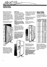
MODEL 590
Figure 14
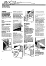
Step 10
Level the unit. Toadjust
height, turn front leveling legs
counterclockwise to raise,
or clockwise to lower. Rear
levellers (rollers) are adjusted
from front of base. Turn Sh6"
hex bolt clockwise to raise
cabinet, counterclockwise to
lower cabinet. See Figure 12.
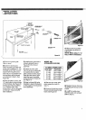
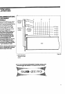
Step 11
Install toe plate as shown in
Figure 15.
Before attaching toe plate
check to ensure drain pan is
installed properly.
I, CAU ONI
Toeplate must be
removable for servicing,
so any flooring must allow
for this removal Refer to
label mounted on
kickplate support for
height clearance.
Step 12
Install grille, step 7.
IMPORTANT'. For Models
511, 532, 542, 550, 561
and 590, reverse step 7
procedure. NOTE: If using
panelized grille refer to
"Grille Panel Installation."
Step 13
Restore power to the wall
outlet.
PANEL
INSTALLATION
Step 14
Apply decorative front panels
(and side panels ifapplicable).
All Sub-Zero units are
manufactured in a manner
to achieve a total built-in
appearance. This allows you
to choose the decorative
material and color application
for the front and sides (if
exposed) for your refrigerator/
freezer.
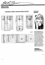
FRONT PANEL
INSTALLATION
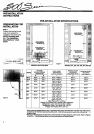
(See "Pre-lnstallation
Specifications" -- for panel
dimensions)
If a metal or other thin material
is used, a filler must be in-
serted behind your panel to
insure a proper fit. All frames
are designed to accept up to
114"material. If a raised, wood
front panel is being used, the
edges must be routed to the
necessary 114"border specifi-
cations. (50# per door panel
maximum weight limit)
NOTE: ROUTING,
RECESSING OR OP-
TIONAL EXTENDED
HANDLES MAY BE
REQUIRED ON RAISED
PANELS FOR FINGER
CLEARANCE UNDER
HANDLE. Refer to Figures
28 and 29 -- "Handle
Recess Specifications
and Recommendation for
Raised Panels."
NOTE: does not apply to
Model 590.
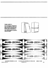
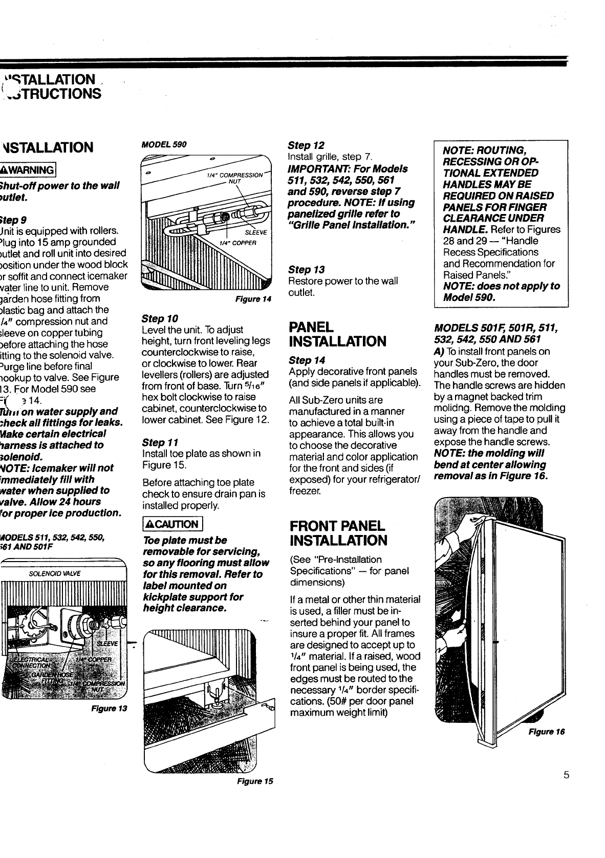
MODELS 501F, 501R, 511,
532, 542, 550 AND 561
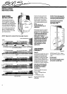
A) Toinstall front panels on
your Sub-Zero, the door
handles must be removed.
The handle screws are hidden
by a magnet backed trim
molidng. Remove the molding
using a piece of tape to pull it
away from the handle and
expose the handle screws.
NOTE: the molding will
bend at center allowing
removal as in Figure 16.
Figure 16
Figure 15 5