


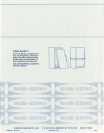
PRE-INSTALLATION
INSTRUCTIONS
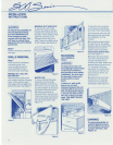
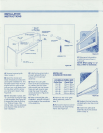
Figure 5
COMPRESSION
FITTING
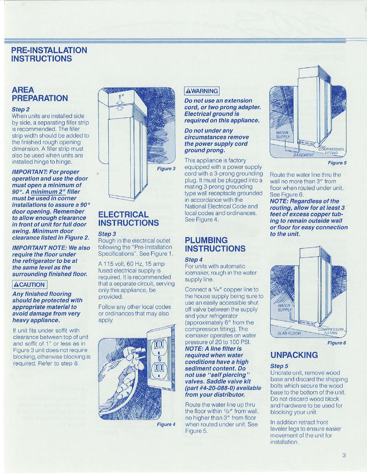
Figure 6
COMPRESSION
FITTING
SLABFLOOR
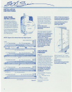
UNPACKING
Step 5
Uncrate unit, remove wood
base and discard the shipping
bolts which secure the wood
base to the bottom of the unit.
Do not discard wood block
and
hardware to be used for
blocking your unit.
In
addition retract front
leveler legs to ensure easier
movement of the unit for
installation.
Route the water line thru the
wall no more than
3"
from
floor when routed under unit.
See Figure 6.
NOTE: Regardless
of
the
routing, allow for
at
least 3
feet
of
excess copper tub-
ing to remain outside wall
or
floor for easy connection
to the unit.
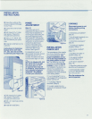
Step 4
For units with automatic
icemaker, rough
in
the water
supply line.
Connect a
'/4" copper line to
the house supply being sure to
use an easily accessible shut
off valve between the supply
and your refrigerator
(approximately
6"
from the
compression fitting). The
icemaker operates on water
pressure of 20 to 100
PSI.
NOTE: A line filter
is
required when water
conditions have
a high
sediment content. Do
not
use
"self
piercing"
valves. Saddle valve kit
(part #4-20-088-0) available
from your distributor.
Route the water line
up
thru
the floor within
'/2" from wall,
no higher than
3"
from floor
when routed under unit. See
Figure 5.
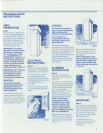
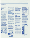
PLUMBING
INSTRUCTIONS
IAWARNINQ]
Do
not
use an extension
cord,
or
two prong adapter.
Electrical ground
is
required on this appliance.
Do
not
under
any
circumstances remove
the
power
supply cord
groundprong.
This appliance
is
factory
equipped with a power supply
cord with a 3-prong grounding
plug.
It
must be plugged into a
mating 3-prong grounding
type wall receptacle grounded
in
accordance with the
National Electrical Code and
local codes and ordinances.
See Figure
4.
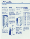
ELECTRICAL
INSTRUCTIONS
Figure 4
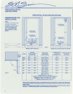
Step 3
Rough
in
the electrical outlet
following the "Pre-Installation
Specifications". See Figure
1.
A 115 volt, 60 Hz, 15
amp
fused electrical supply
is
required.
It
is
recommended
that a separate circuit, serving
only this appliance, be
provided.
Follow any other local codes
or ordinances that may also
apply.
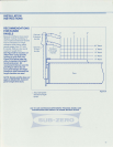
AREA
PREPARATION
Step 2
When units are installed side
by side, a separating filler strip
is
recommended. The filler
strip width should be
added
to
the finished rough opening
dimension. A filler strip must
also be used when units are
installed hinge to hinge.
IMPORTANT: For
proper
operation
and
use the door
must open
a minimum
of
90
0
•
A minimum
2"
filler
must be used in corner
installations to assure
a
90
0
door opening. Remember
to allow enough clearance
in front
of
unit for full door
swing, Minimum door
clearance listed in Figure
2.
IMPORTANT NOTE:
We
also
require the floor under
the refrigerator
to
be
at
the same level
as
the
surrounding finished floor.
IACAUTION I
Any
finished flooring
should be protected with
appropriate material to
avoid damage from very
heavy appliance.
If
unit fits under soffit with
clearance between top of unit
and soffit of 1" or less as
in
Figure 3 unit does not require
blocking, otherwise blocking is
required. Refer to step
8.
3