


INSTALLATION
INSTRUCTIONS
INSTALLATION
IAWARNINGI
Shut-off
power
to
the wall
outlet.
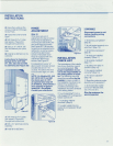
Step
9
Unit
is
equipped with rollers.
Plug into 15
amp
grounded
outlet and roll unit into desired
position under the wood block
or soffit and connect icemaker
water line to unit. Remove
garden hose fitting from
plastic bag and attach the
'/4" compression nut and
sleeve on
copper
tubing
before attaching the hose
fitting to the solenoid valve.
Purge line before final
hookup to valve. See Figure
13. For Model 590 see
Figure 14.
Turn
on water
supply
and
check
all
fittings
for
leaks.
Make certain electrical
harness Is attached to
solenoid.
NOTE: Icemaker
will
not
immediately
fill
with
water when
supplied
to
valve.
Allow
24
hours
for
proper
ice
production.
MODELS 511, 532, 542, 550,
561
AND501F
SOLENOID
VALVE
Figure
13
MOOEL590
Figure
14
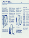
Step
10
Level the unit.
To
adjust
height, turn front leveling legs
counterclockwise to raise,
or clockwise to lower. Rear
levellers (rollers) are adjusted
from front of base.
Turn
5h6"
hex bolt clockwise to raise
cabinet, counterclockwise to
lower cabinet. See Figure 12.
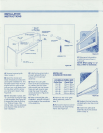
Step
11
Install toe plate as shown
in
Figure 15.
Before attaching toe plate
check
to ensure drain pan
is
installed properly.
IACAunON
I
Toe
plate
must
be
removable
for
servicing,
so
any
flooring
must
allow
for
this removal. Refer
to
label
mounted
on
kickplate
support
for
height
clearance.
Figure 15
Step
12
Install grille, step
7.
IMPORTANT:
For
Models
511, 532, 542, 550,
561
and
590, reverse step 7
procedure. NOTE:
If
using
panelized
grille
refer to
"Grille Panel Installation.
"
Step
13
Restore power to the wall
outlet.
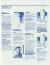
PANEL
INSTALLATION
Step
14
Apply decorative front panels
(and side panels if applicable).
All Sub-Zero units are
manufactured
in
a manner
to achieve a total built-in
appearance. This allows you
to choose the decorative
material and color application
for the front
and
sides (if
exposed) for your
refrigeratorl
freezer.
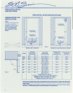
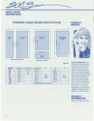
FRONT PANEL
INSTALLATION
(See "Pre-Installation
Specifications" - for panel
dimensions)
If
a metal or other thin material
is
used, a filler must be
in-
serted behind your panel to
insure a proper
fit.
All frames
are designed to accept
up
to
'/4" material. If a raised, wood
front panel
is
being used, the
edges must
be
routed to the
necessary
'/4" border specifi-
cations. (50# per
door
panel
maximum weight limit)
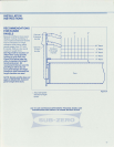
NOTE: ROUTING,
RECESSING
OR
OP·
TlONAL EXTENDED
HANDLES MAY BE
REQUIRED ONRAISED
PANELS FOR FINGER
CLEARANCE UNDER
HANDLE.
Refer to Figures
28 and 29 - "Handle
Recess Specifications
and Recommendation for
Raised Panels."
NOTE: does
not
apply
to
Model 590.
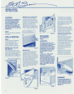
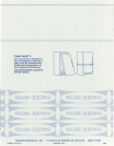
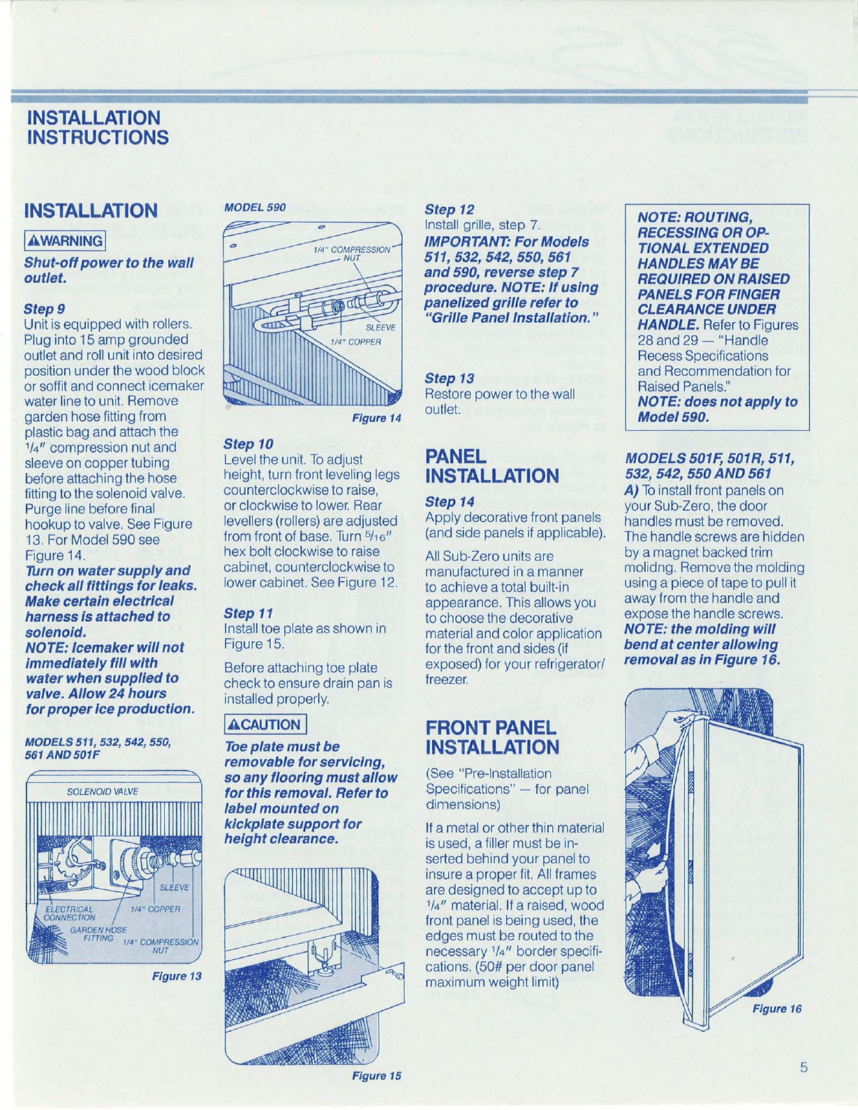
MODELS
501F,
501R,
511,
532, 542, 550
AND
561
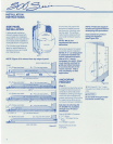
A)
To
install front panels on
your Sub-Zero, the
door
handles must be removed.
The handle screws are hidden
by a magnet backed trim
molidng. Remove the molding
using a piece of tape to pull it
away from the handle and
expose the handle screws.
NOTE: the
molding
will
bend
at
center
allowing
removalas
in
Figure 16.
5