


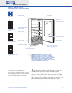
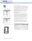
Planning Information
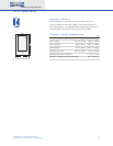
Built-In Model 601RG
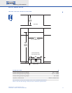
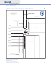
Dimensions in parentheses are in
millimeters unless otherwise specified.
5
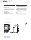
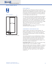
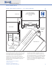
INSTALLATION NOTES
R
efer to the illustrations and specifications
for overall dimensions, finished rough opening
dimensions and installation specifics.
A
llow the door to open a minimum of 90˚ or
you'll have problems removing drawers. With
the door opening at 90˚, you may have to move
drawers slightly to clear the door interior. Refer
to the minimum door swing clearance in the
specifications chart.
For corner installations, allow for a minimum
3" (76) filler so that the door can open to 90˚.
If you're using raised panels, consider using a
wider filler. A 90˚ door stop is available as an
accessory.
When units are installed side by side, a filler
strip is recommended. The width of this filler
strip will vary depending on the configuration
and panels you use. An anchoring kit may also
be used to attach two units together. This kit is
available through your Sub-Zero dealer.
Be sure to add the filler strip width to your
finished rough opening dimension. In any side-
by-side installation without a filler strip, add an
additional
1
/2" (13) to y
our combined number
s.
This will allow for the proper width.
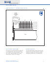
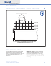
Refer to the full-scale illustrations at the end
of this section for specifics on door openings
and filler size alternatives.
If your client has chosen the stainless steel
design, the unit will be shipped complete with
wrapped stainless steel doors and handle
hardware. You will not have to install front
panels.
If y
our client has chosen the fr
amed or
overlay design, you will be adding front panels
to give the unit the custom Sub-Zero look. The
overlay design also allows you to add your own
handles, or you may choose accessory handles
av
ailable through your Sub-Zero dealer. Refer to
pages
6
–
10 for detailed information on adding
panels.
T
he refrigerator door panel must include a
cut-out to accommodate the window. Refer to
the panel specifications for exact dimensions.
The glass portion of the door must be exposed
a
nd not covered by any part of the panel.
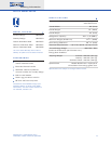
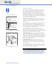
A 115 volt, 60 Hz, 15 amp electrical supply
is required. The supply circuit for this appliance
must be protected by a 15 amp fuse or circuit
breaker. It is recommended that a separate
circuit, serving only this appliance, be provided.
All Built-In models are equipped with a 6'
(1.8 m) power supply cord with a 3-prong
grounding plug which must be plugged into a
mating 3-prong grounding type wall receptacle.
Locate electrical within the shaded area shown
in the installation illustration.
You must follow all National Electrical Code
regulations. In addition, be aware of local codes
and ordinances when installing your service.
To prevent the unit from tipping forward and
provide a stable installation, the unit must be
secured in place with an anti-tip blocking kit. If
there is a solid soffit above the unit with clear-
ance between the unit and the soffit of 1" (25)
or less, you won't need to block the unit.
For installations with clearances of more
than 1" (25), you must block the unit with the
anti-tip bloc
king kit (wood block and hardware)
provided with each Built-In unit.
Refer to the Built-In Installation Instructions
packed with the appliance, which provides
step-by-step procedures for making sure the
unit is installed properly.