


6
INSTALLATION
Plumbing
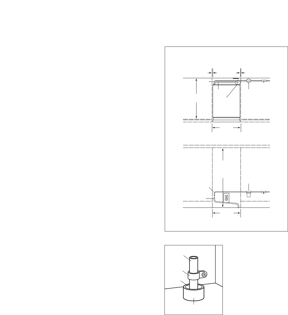
Model 315–Gravity Drain Model
The drain and inlet water tubes must be plumbed before
connecting to the ice maker. All horizontal runs of drain
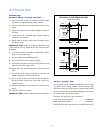
lines must have a 1/4" per foot fall. An air gap will likely
be required between the ice maker drain tube and the
drain/waste receptacle. A stand pipe with a trap below it
would be acceptable for the drain/waste receptacle.
IMPORTANT NOTE: Poor draining will cause a high rate
of ice melting in the bin.
1) Place ice maker in front of installed location. Adjust
leg levelers to approximately correct position.
2) Remove door with hinges, control knob, control panel,
access panel and lower stainless face plate.
3) Route water inlet line, which should be a 1/4" O.D.
copper tube, from wall through ice maker to the front.
4) Route drain line from wall position through ice maker.
NOTE: if using a long horizontal run (more than 5 feet)
the drain should be vented at back of cabinet.
5) If electrical outlet for ice maker is behind the cabinet,
plug in the ice maker now.
6) Push ice maker into installed position.
7) Cut off water inlet line at required length.
8) Flush water line. Place flare nut on inlet water line and
flare the end of the copper tube.
9) Attach flare nut to the male flare on the inlet water
valve.
10) Cut off the drain tube to the required length.
11) Connect the 5/8" drain tube to the bin drain fitting at
the bottom of the bin. Secure with hose clamps.
Be certain that the drain tube is pushed up well past the
barbs on the drain fitting. If needed to ease installation,
soak the drain hose in hot water just before connecting to
the fitting.
12) Turn on the water supply and check for leaks.
13) Replace door with hinges, control knob, control panel,
access panel and lower stainless face plate. Level as
needed.
IMPORTANT NOTE: All plumbing must meet local codes.
15
1
/4"
(387) MIN.
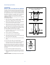
FRONT VIEW
SHUT-OFF
VALVE
WATER
FILTER
WATER
INLET TUBE
DRAIN
TUBE
TOP VIEW
SHUT-OFF
VALVE
WATER
FILTER
34
1
/2"
(876) NOMINAL
33
3
/4"
(857) MIN.
15
1
/4"
(387) MIN.
24"
(610)
1
/8"(3)
WATER
INLET
TUBE
DRAIN
TUBE
LOCATE DRAIN
WITHIN 2" DIA.
AREA 23" BACK
FROM FRONT
OF UNIT
PRE-INSTALLATION SPECIFICATIONS
MODEL 315 (GRAVITY DRAIN)
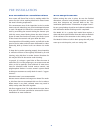
Drain Tube
Clamp
Drain
Stand Pipe
Drain Tube Detail