


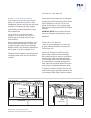
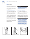
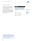
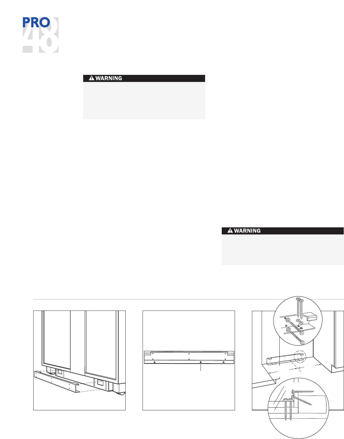
WOOD FLOOR APPLICATIONS
Use the twelve #12 x 2
1
/2" wood screws and
the twelve #12 flat washers provided. Drill
p
ilot holes
3
/1
6
"
(5) diameter maximum and be
sure that the screws penetrate through the
flooring material and into the wall plate a
m
inimum of
3
/4"
(19). Be sure that the screws
hold tight. Refer to the illustration below.
IMPORTANT NOTE:
If the wood screws do not
hit a wall stud in any of the upper holes on the
anti-tip bracket, use the provided #8–18 x 1
1
/4"
wood screw, #12 flat washer and nylon zip-it
wall anchor in its place.
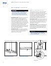
IMPORTANT NOTE:
In some installations the
subflooring or finished floor may necessitate
angling the wood screws used to fasten the
anti-tip bracket to the back wall. Refer to the
illustration below.
8
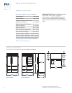
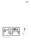
ANTI-TIP BRACKET
INSTALLATION
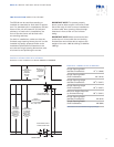
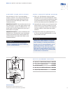
IMPORTANT NOTE:
Placement of the anti-tip
bracket is critical to a stable installation. It
must be installed exactly 26" (660) from the
front of the face frame of the unit to the back
of the anti-tip bracket. Also, the centering line
on the lower flange of the anti-tip bracket must
be centered in the rough opening. Failure to
properly position the anti-tip bracket will
prevent it from engaging the unit. Be sure that
the anti-tip bracket is installed on a solid base.
Refer to the illustrations below.
IMPORTANT NOTE:
For a stable installation,
be sure to use all anti-tip bracket hardware as
instructed for wood or concrete floors to
properly secure the bracket.
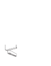
To prevent the PRO 48 from tipping
forward and provide a stable installation,
the unit must be secured in place with
the anti-tip bracket shipped with the unit.
W
ood floors
Make sure that there are no electrical
wires or plumbing in the area which the
screws could penetrate.
PRO 48 INSTALLATION INSTRUCTIONS
C
L
Anti-tip bracket centerline
Anti-tip bracket alignment
C
L
WOOD
FLOOR
Finished Flooring
Underlayment
Sub Flooring
Wall Plate
23
3
/4"
(603)
23
3
/4"
(603)