


11
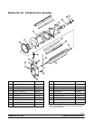
Models 340, 341, 342 Operating Procedures
020807
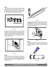
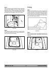
Step 3
If the blades are in good condition, install the scraper
blade clip over the s craper blade. Place the rear
scraper blade over the rear holding pin (knife edge to
the outside). Holding the blade on the beater, turn it
over and install the front blade the same way.
Figure 4
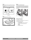
Holding the blade in position, insert the beater
assembly into the freezing cylinder and slide it into
position over the drive shaft. Turn the beater slightly to
be certain that the beater is properly seated. When in
position, the beater will not protrude beyond the front
of the freezing cylinder.
10362
Figure 5
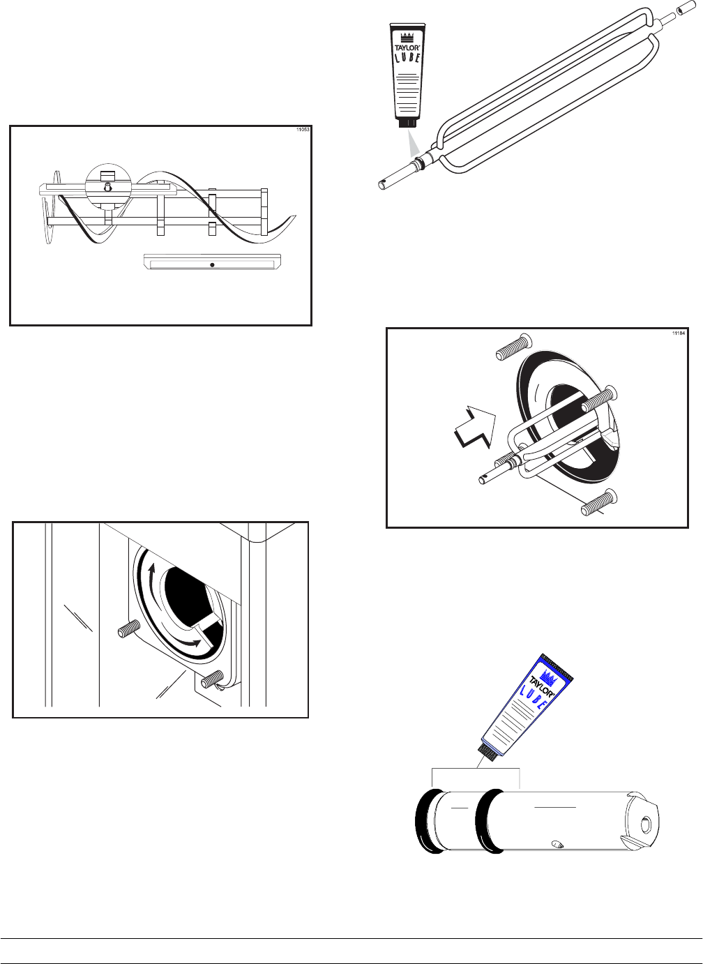
Step 4
Install the torque rotor shaft. Slide the o-ring into the
groove on the front of the shaft and lubricate these
parts to prevent leaking. Place the white, plastic guide
bearing on the rear of the rotor shaft. DO NOT lubricate
the guide bearing.
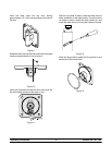
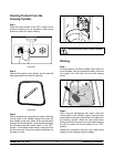
Figure 6
Insert the torque rotor shaft, plastic bearing end first,
making sure that it fits into the hole in the beater drive
shaft. Rotate it several times to check for proper
positioning. The hole in the torque rotor shaft should be
in the 12 o’clock position.
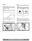
Figure 7
Step 5
Assemble the freezer door with the “Ice Buster” (door
spout clearing device). To assemble the door with the
ice buster, install the o-rings on the draw valve and
lubricate.
Figure 8