


ENGLISH
3736
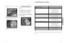
If the equipment does not work, advise the
Technical Service Department of the problem
you have observed, indicating,
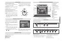
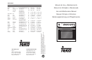
1 Serial number (S-No)
2 Appliance model. (Model)
That you will find engraved on the
characteristics plaque. This plaque is found
on the lower part of the oven and can be seen
when the door is open.
To help in identifying the oven, we recommend
you write the following data:
S-No:
Mod:
The item that you have bought meets the
European directives on electrical material
safety (73/23/CEE) and electromagnetic com-
patibility (89/336/CEE).
Technical Information Installation
This information is purely for a qualified
technician, as the person responsible for
assembly and electrical connection. If you
install the oven yourself, the manufacturer will
not be held responsible for any possible
damage.
•To unpack the oven, pull the tab located on
the lower part of the box. To move it, hold it
by the lateral handles and never by the
oven door handle.
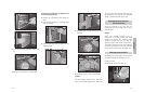
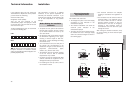
• An opening is made in the kitchen unit with
the dimensions appearing on the figure,
ensuring a minimum depth of 580 mm.
(See figures 1 and 2 describing oven fitting
on the back cover).
•To fit multifunction ovens, the back part of
the kitchen unit corresponding to the
shaded area of figure 3, must not have any
projections (reinforcements, pipes,
sockets, etc). (See the back cover).
• The adhesive used for the plastic covering
of the mit must be able to withstand
temperatures of up to 85ºC.
• Our ovens may only be combined with TEKA
cookers, otherwise the equipment may be
damaged and safety compromised.
•For installing the work top cooker, refer to
its instruction manual.
Before Making the Installation.
Comments
• The electrical connection has adequate
earthing in accordance with regulations in
force.
• The connection must be carried out with an
omnipolar switch, of an adequate size for
the current drawn and with a minimum
aperture between contacts of 3mm for
disconnection in the case of emergency,
cleaning or bulb exchange. Under no
circumstances must the earth wire pass
through this switch.
After making the electrical connection, verify
the correct working of all the electrical parts
of the oven.
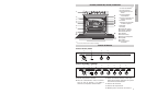
The installer must check that:
• The voltage and cycles of the mains supply
correspond to that indicated in the
characteristics plaque.
• The electrical installation can stand the
maximum power indicated in the
characteristics plaque.
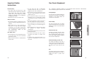
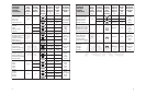
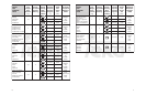
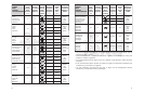
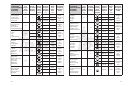
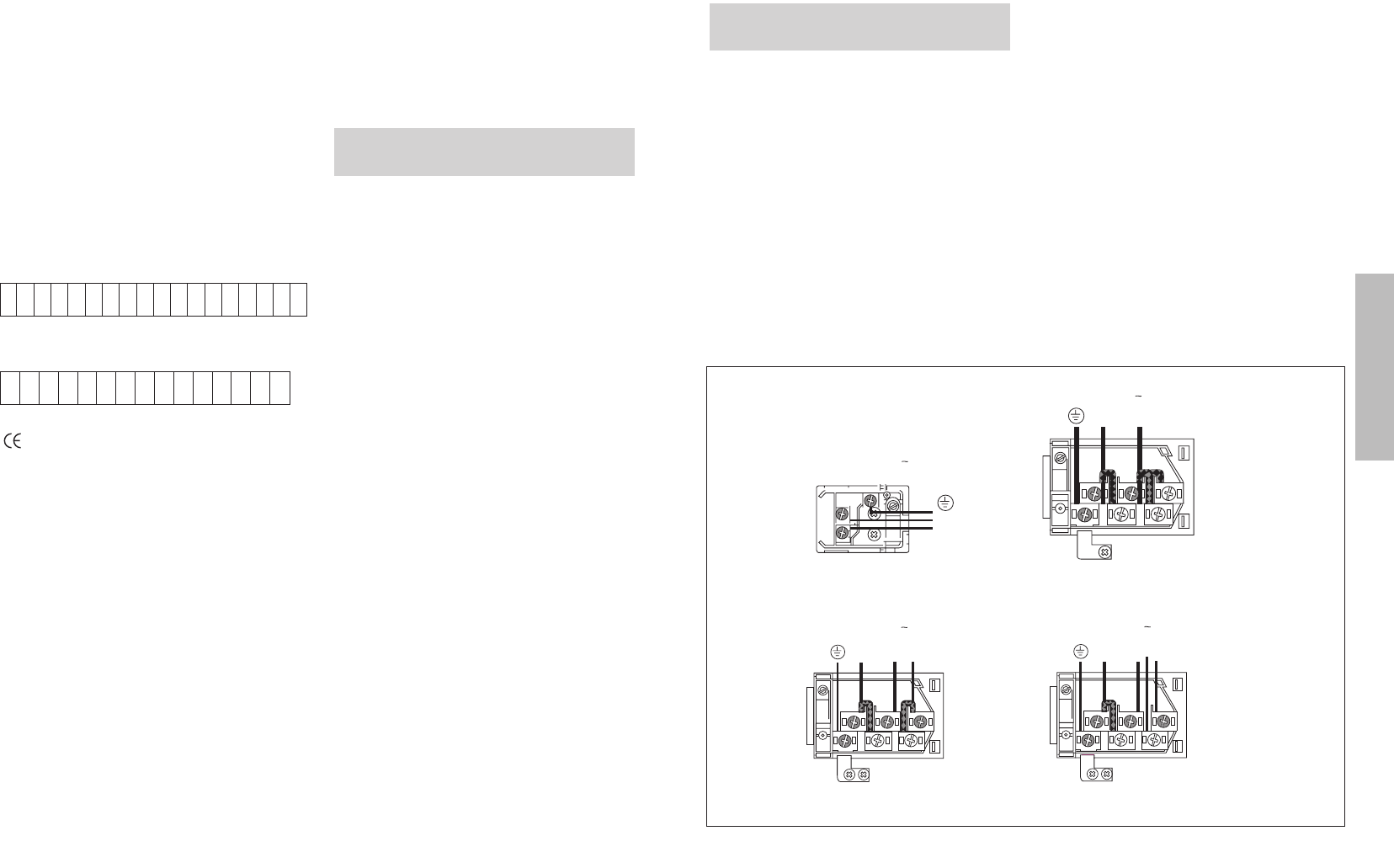
•To connect the oven to the electrical circuit,
the installer must use a T150 type supply
cable. The connection diagram is shown in
the following figure:
Electrical Connection.
Legal Requirements
230 V 1
N
L
3 x 4mm
2
T 1503 x 1,5mm
2
T 150
N
L
230 V 1
N
L
2 L1
400 V 2N
4 x 2,5mm
2
T 150
N
L
3 L1
400 V 3N
5 x 1,5mm
2
T 150
L2