


STEP 3
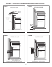
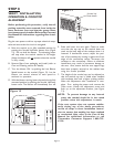
PREPARE DUCT CUTOUTS IN CABINET
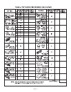
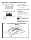
TABLE 4
INTEGRAL BLOWER VTN600CVA
C D E F G H
UCV30 7-1/2 6 1/4 15-1/2 9 -
UCV36 7-1/2 6 1/4 15-1/2 9 -
UCV45 7-1/2 6 1/4 15-1/2 9 -
REMOTE BLOWER VTR600R OR VTR1000Q
C D E F G H
UCV30 7-1/4 6 - 12-1/4 12-1/4 3
UCV36 7-1/4 6 - 12-1/4 12-1/4 3
UCV45 7-1/4 6 - 12-1/4 12-1/4 3
Page 10
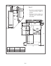
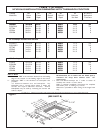
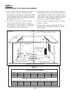
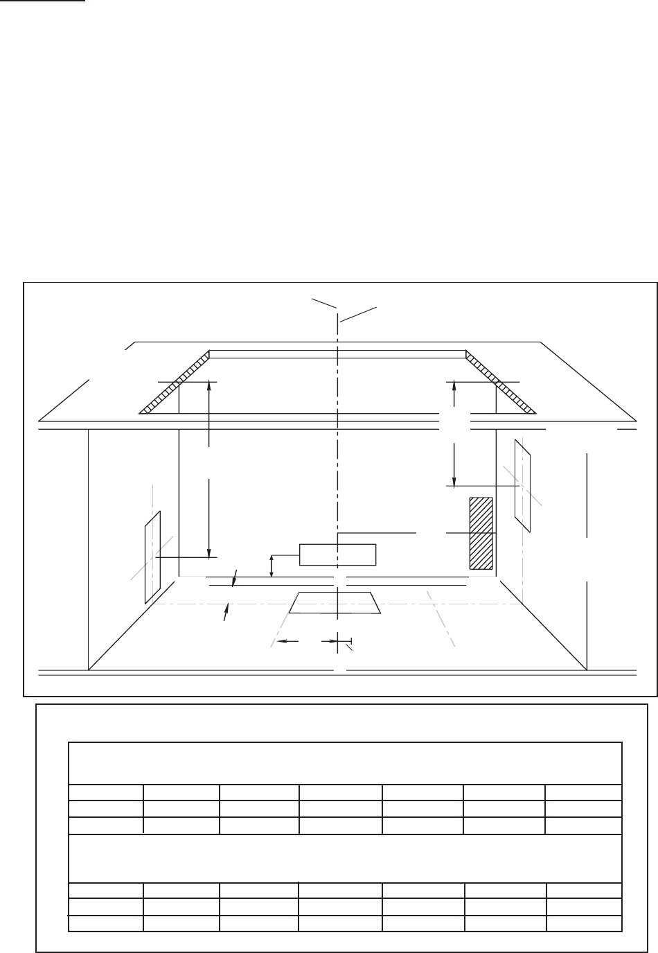
A. Refer to Figure 9. Drop a plumb-line from Point "P"
at the center of the rear countertop cutout.
Mark this point on the bottom of the cabinet. Draw
Line AA through this point and parallel to the front
of the cabinet. Through the same point draw Line
BB perpendicular to Line AA.
B . Use Table 4 to layout the necessary cabinet
cutouts for the ductwork. Where a range of
measurements is noted, choose a measurement
that allows best clearance from wall studs, floor
joists, utilities, or other obstructions.
C. Temporarily set intake and cooktop in place and
attach integral blower (or duct transition fitting if a
remote blower is installed). Refer to steps 6 and 7.
Verify that the duct cutouts as marked will match
the hardware installation. Adjust the duct cutout as
necessary to match hardware installation.
D. Remove temporarily placed hardware and make
cutouts in cabinet.
E . Make all other cabinet modifications needed to
provide proper clearances for drawers or remov-
able shelving.
Figure 9
Cabinet Back
Left Side
Note: Centerlines of
Rectangular Duct Shown
Countertop
Surface
Point "P" (Center of Rear Cut-line)
L
C
Right Side
Receptacle
Location
F
CABINET CUT-OUT FOR DUCTWORK
G
Cabinet Bottom Shelf
Plumb line to
intersection A-A &
B-B
C
A
A
H
E
B
Adjustable Within Range
B
B
D
30"