


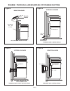


STEP 7
MOUNT INTEGRAL BLOWER OR
Remote Blower Transition
MOUNT INTEGRAL BLOWER OR Remote
Blower Transition
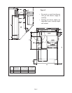
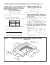
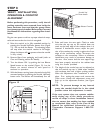
Integral Blower VTN600CVA Only
A. Place blower in front of intake inside of cabinet,
take conduit and blower wires and guide them
towards the right at the floor of the cabinet.
B. On each side of blower housing there is a
flanged edge. When placing the housing onto the
intake, these flanges need to be positioned in line
with intake flanges.
C. Place the support bars over the screws on the
left and right sides of the housing. Secure blower
with wing nuts.
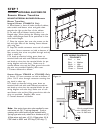
D. Snap 90
0
conduit connector onto end of conduit
and wires. Secure connector to hold at bottom of J-
Box, ensuring that wires are pulled through and any
slack is taken up.
E. To hook up electrical wiring, press down on
terminal block tab with small flathead screwdriver
and hook up wires into the terminal blocks (as per
wiring diagram and color key). Make sure to
connect blower wire and the J-Box ground wire with
the wire nut provided. Replace J-Box cover.
F. Connect ductwork to blower.
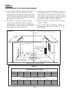
Remote Blower VTR600R or VTR1000Q Only
A. Secure 1/2" box connector to hold at bottom of
J-Box. Pull 5 wires through connector ensuring that
any slack is taken up.
B. To hook up electrical wiring, press down on
terminal block tab with small flathead screwdriver
and hook up wires into the terminal blocks (as per
wiring diagram and color key). Make sure to con-
nect blower wire and the J-Box ground wire with the
wire nut provided. Replace J-Box cover.
C. Connect ductwork to blower.
Page 12
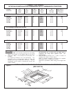
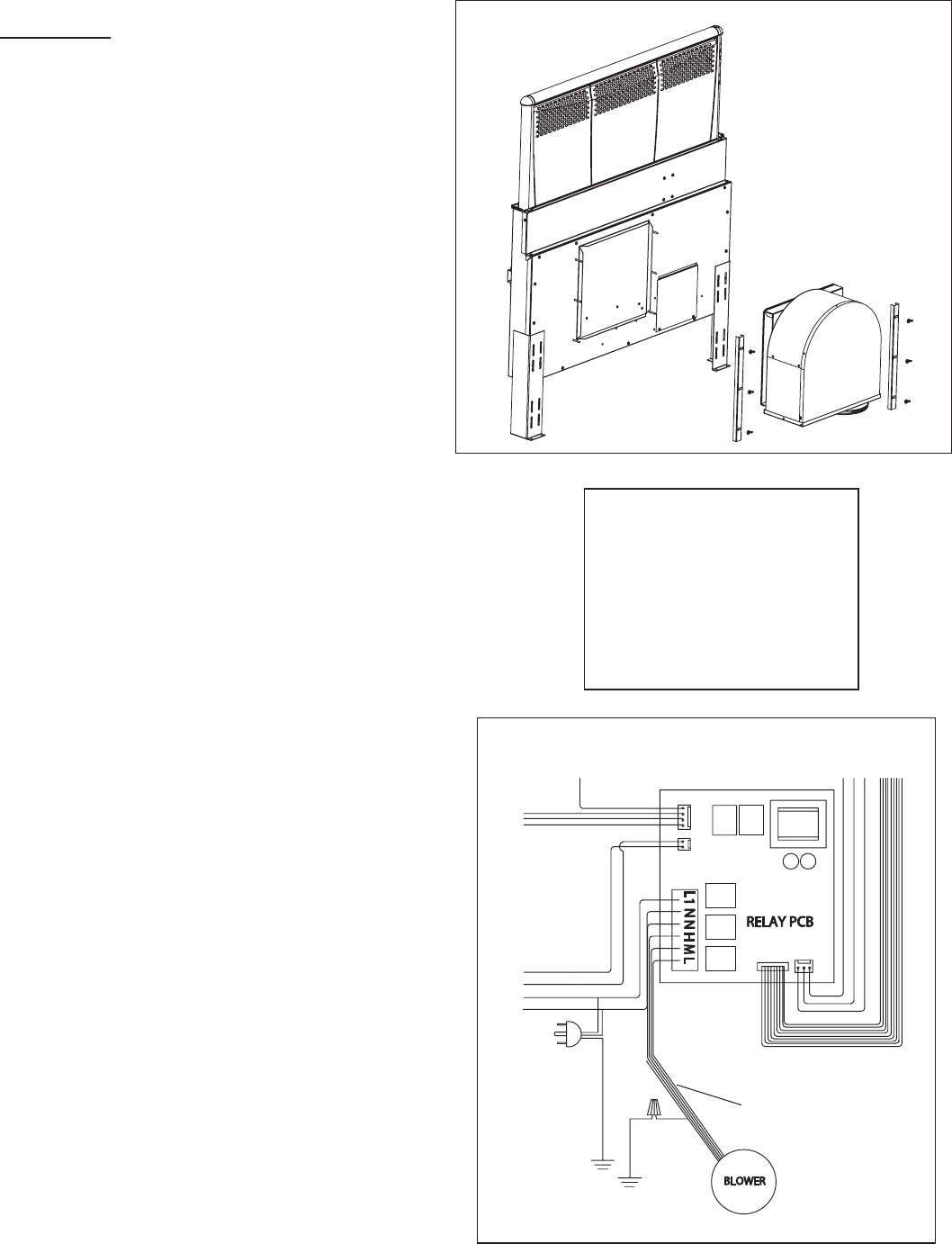
Figure 10
Figure 11
Wire to remote blower
min. 18 AWG wire
max. 14 AWG wire
Note: Use spring type wire nuts supplied to con-
nect wires per Fig. 11 wiring diagram. (Lost or
missing wire nuts should only be replaced with:
Spring type wire nuts, rated for a minimum of (2)
#18ga wires and max. of (4) #14ga wires, UL &
CSA rated to 600V and 302 deg.F/150 deg. C).
UCV WIRING DIAGRAM
COLOR KEY
Red = Low
Blue = Medium
Black = High
White = Neutral
Green = Ground