


SECTION 2 - INSTALLATION
10
E. Electrical Connection
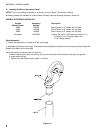
Be sure your electrician provides the proper wire gauge with a capacity for carrying the voltage required. Wire capacity
is listed on the serial number data plate. Wire capacity and electrical specifications are listed in Section 1 of this manual.
Also check local and state codes for proper wire size.
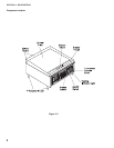
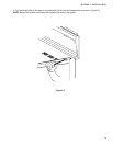
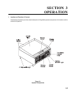
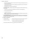
The incoming power wires from the circuit breaker box to the griddle are inserted into the rear or bottom of the griddle
as shown below.
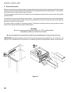
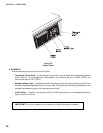
The location of the main terminal block is shown below . For access to the terminal block remove the grease drawer,
open the door and then slide the drawer channel out as shown below. Connect the wires as shown on the electrical
schematic in Section 5 of this manual.
No internal fusing is provided on countertop griddles. Therefore the installing contractor must provide the proper
disconnect as may be required by state and local codes.
CAUTION:
Be sure the main power disconnect switch is in "OFF" position before
attempting to make any electrical connections.
Be sure all electrical connections are tight and are positioned so they will not short out.
IMPORTANT: All griddles are factory wired for 3 Ph and must be rewired during installation for 1 Ph connection. The
wiring for 1 Ph connection and 3 Ph connection for all models is shown on the Schematics in Section 5 of this manual.
Figure 2-3