


ENGLISH
2
Control panel
mounting screws
II. INSTALLATION
IMPORTANT
IT IS THE
CUSTOMERS RESPONSIBILITY TO REPORT ANY
CONCEALED OR NON-CONCEALED DAMAGE TO THE FREIGHT
COMPANY.
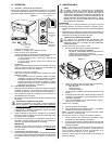
A. Installation Options and Kit Availability
Your hot food server is shipped from the factory with 4 NSF-listed
plastic legs, which may be used on single-unit or two-stack installa-
tions. The following kits are available from Toastmaster for additional
installation options:
P/N ACCHFSC Casters kit (for 1-4 units)
P/N ACCHFS6 6 legs kit (for 1-4 units)
P/N ACCHFS9 9 legs kit (for 1-4 units)
All hot food server installations REQUIRE the unit(s) to be mounted
on legs or casters prior to operation. The allowed installation configu-
rations are:
Supplied Casters 6 legs 9 legs
4 legs kit kit kit
Single unit YES YES YES YES
Two-stack YES YES YES YES
Three-stack NO YES YES YES
Four-stack NO YES YES YES
CAUTION
STACKING MORE THAN FOUR SERVERS IS NOT PERMITTED.
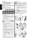
B. Legs/Casters Assembly
1. To install the supplied 4/102mm legs (1-2 units only), thread the
legs into the four holes on the bottom of the hot food server. An
illustration of the server with the supplied legs installed is shown
on the cover of this Manual. For a Two-Stack installation, attach
the legs to the bottom server only.
2. To install an optional Legs Kit or Casters Kit, refer to the instruc-
tions provided with the Kit.
C. Stacking the Hot Food Servers (2-4 units only)
CAUTION
If you have installed the optional Casters Kit,
check that the casters
are locked before stacking the hot food servers.
Perform the following steps, starting with the server that has legs/
casters installed:
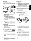
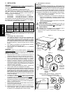
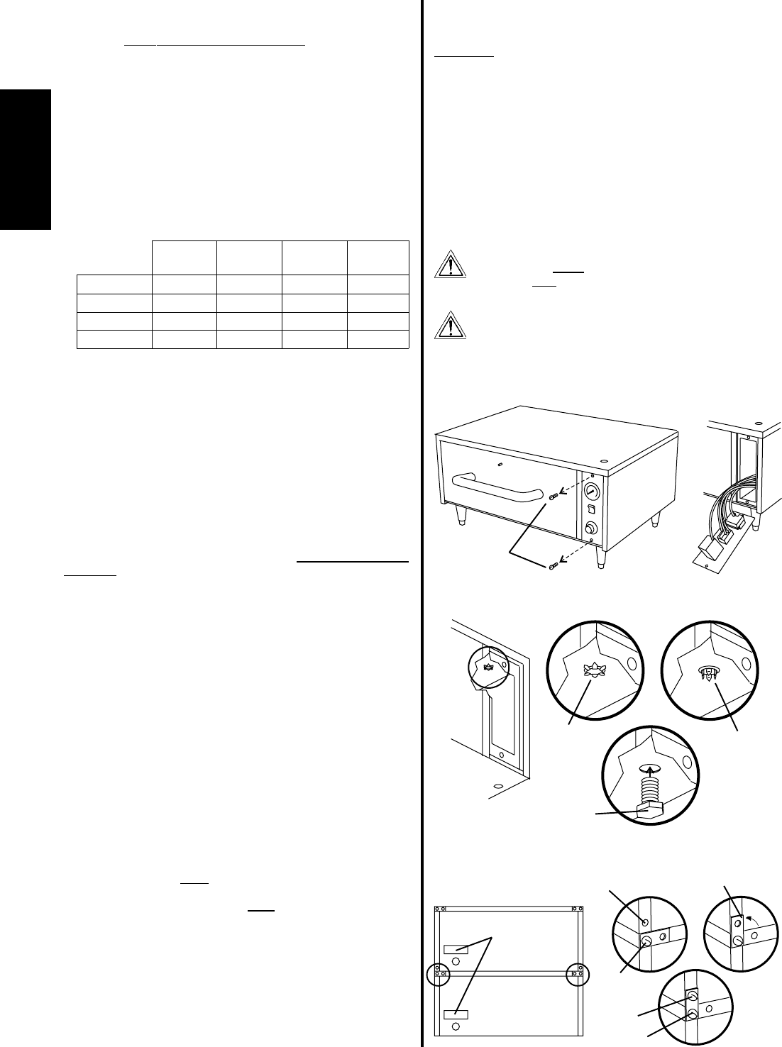
1. Remove the two screws that hold the control panel in place. Be
sure to retain the screws. See Figure 2.
2. Gently pull the control panel out from the front of the unit and
allow it to hang by the wiring. DO NOT stretch or disconnect the
wiring! See Figure 2.
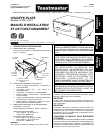
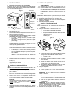
3. Remove the cap plug from the top panel of the unit. To remove
the plug, bend the tines on the underside of the plug in towards
the center using a pair of pliers. Then, lift the cap free and dis-
card it. See Figure 3.
4. Place a hot food server atop the unit. Check that all four sides of
the units are aligned.
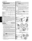
5. Attach the two units together by inserting the supplied 3/8 bolt
from inside the control panel opening of the lower server, as shown
in Figure 4. The bolt passes through the hole in the top panel
and into the threaded leg hole in the floor of the upper unit. Tighten
the bolt to a LOOSE fit to allow the position of the units to be
adjusted.
6. At the rear of the upper server, remove the screws from BOTH
bottom rear corners, as shown in Figure 4. Then, loosen (do not
remove) the two screws on the lower server that hold the stack-
ing clips in place.
7. Reposition the stacking clips as shown in Figure 4, and replace
the two screws that you removed in Step 6. Tighten all four
screws.
8. Tighten the 3/8 bolt (that you installed in Step 5) to secure the
units together.
9. Replace the control panel, and fasten it in place with its screws.
10. Repeat Steps 1-9 until all units are stacked. Note that the cap
plug will remain in place on the top server in the stack.
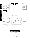
D. Electrical Connection
IMPORTANT
THE ELECTRICAL CONNECTION TO THE HOT FOOD SERVER
REQUIRES A CIRCUIT BREAKER/FUSED DISCONNECT. ELEC-
TRICAL SPECIFICATIONS ARE LISTED ON THE SERIAL PLATE
(SHOWN IN FIGURE 4), AND IN SECTION I OF THIS MANUAL.
CONSULT ALL APPLICABLE NATIONAL AND LOCAL CODES FOR
FURTHER ELECTRICAL CONNECTION REQUIREMENTS.
1. Before proceeding with the electrical connection, check the fol-
lowing for each hot food server:
a. Check that the electrical supply matches the hot food
servers requirements. Refer to the serial plate (Figure 4)
and to the electrical specifications shown in Section 1 of
this Manual.
b. Check that the appropriate receptacle is available for the
power cord plug.
WARNING
ENSURE THAT
BOTH THE CIRCUIT BREAKER/FUSED DIS-
CONNECT
AND THE POWER ON/OFF (I/O) SWITCH ARE
IN THE OFF (O) POSITION BEFORE PROCEEDING.
WARNING
ENSURE THAT ANY PACKING MATERIAL HAS BEEN RE-
MOVED FROM INSIDE THE CABINET AND FOOD TRAY.
3. Insert (each) power cord plug into its receptacle.
Figure 2
Figure 3
2. To remove,
bend tines in
towards
center of plug
1. Cap plug
shown
in place
3. After stacking,
insert bolt
through cap hole
Figure 4 (left side shown - reposition brackets on BOTH sides)
Underside
of server
Control
panel
opened
Data plate
1. Remove
2. Loosen
3. Reposition
4. Replace
5. Tighten