


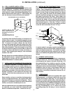
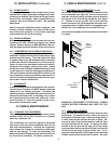
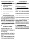
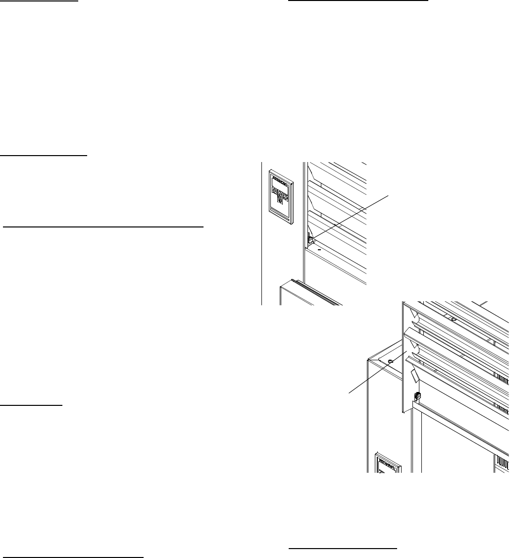
IV. a - CLEANING THE CONDENSER (cont’d):
two screws located on both sides at the bottom of the
louver assembly (see figure 6). Once the screws are
removed, the panel can be pivoted upwards allowing
full access to the front facing condenser (see figure
7). Vacuum or brush any dirt, lint or dust from the
finned condenser coil, the compressor and other cool-
ing system parts. If significant dirt is clogging the con-
denser fins, use compressed air to blow this clear.
Lower louver assembly and replace the screws to hold
it in place.
WARNING: DISCONNECT ELECTRICAL POWER
SUPPLY BEFORE CLEANING ANY PARTS OF THE
UNIT.
IV. b -
HINGE REPLACEMENT:
Both the door and hinge can be easily removed from
the cabinet. To remove the door, remove the plug at
the bottom of the top hinge. Inside the hinge there is
a small screw which secures the door in place. Re-
move this with a flat head screwdriver and the door
can then be lifted off the hinge. To remove the door
portion of the hinge from the door, lift off the hinge
cover and then remove the three Phillips head screws
which secure the hinge in place on the door. To re-
move the cabinet portion of the hinge, remove the three
Phillips head screws which hold it in place. On solid
Fig. 7
Lift-Up Louver
Assembly
-4-
III. i - POWER SUPPLY:
The supply voltage should be checked prior to con-
nection to be certain that proper voltage for the cabi-
net wiring is available (refer to the serial tag to deter-
mine correct unit voltage). Make connections in ac-
cordance with local electrical codes. Use qualified
electricians.
Use of a separate, dedicated circuit is required. Size
wiring to handle indicated load and provide neces-
sary overcurrent protector in circuit (see amperage
requirements on the unit’s serial tag).
III. j - WIRING DIAGRAM:
Refer to the wiring diagram for any service work per-
formed on the unit. Should you require one, please
contact Traulsen Service at (800) 825-8220, and pro-
vide the model and serial number of the unit involved.
III. k - COMPRESSOR HOLD DOWN PROVISIONS:
To protect the compressor during transit, some self-
contained Traulsen models have compressors tight-
ened down at the factory. The hold down bolts used
to tighten these must be loosened before operation
to allow the vibration eliminators to funtion properly.
Failure to loosen the hold down bolts could result in
refrigerant line leakage, vibration and noise. Check
the top to be sure all factory installed blocking (if used)
is also removed. Likewise, check the compressor en-
closure of bottom mounted units (RFD models) to be
sure all packing is removed and that compressors se-
cured to the base of condensing unit are free to oper-
ate on their vibration eliminators.
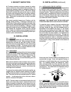
III. l - CLEARANCE:
In order to assure optimum performance, the condens-
ing unit of your Traulsen unit MUST have an adequate
supply of air for cooling purposes. Therefore, the
operating location must either have a minimum of 12”
clearance overhead of the condensing unit or allow
for unrestricted air flow at the back of the unit. Clear-
ance of at least 12” above is required in order to per-
form certain maintenance tasks.
IV. CARE & MAINTENANCE
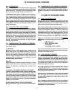
IV. a - CLEANING THE CONDENSER:
The most important thing you can do to insure a long,
reliable service life for your Traulsen is to regularly
clean the condenser coil.
The condensing unit requires regularly scheduled
cleaning to keep the finned condenser clean of lint
and dust accummulation. Keeping the condenser
clean allows the cabinet to operate more efficiently
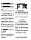
and use less energy. To clean the condenser, first
disconnect electrical power to the cabinet and lift up
the front louver as sembly. To lift this, remove the
III. INSTALLATION (continued) V. CARE & MAINTENANCE (cont’d)
Fig. 6
Remove
Screws